


Isys
®
G-Series Touchpanel Interface Crestron TPS-GA-TPI
30 • Isys
®
G-Series Touchpanel Interface: TPS-GA-TPI Operations Guide – DOC. 6501
• If the rack is provided with stabilizing devices, install the stabilizers before
mounting or servicing the unit in the rack.
NOTE: If rack mounting is not required, rubber feet are provided for tabletop
mounting or stacking. Apply the feet near the corner edges on the underside of the
unit.
NOTE: Reliable earthing of rack-mounted equipment should be maintained.
Particular attention should be given to supply connections other than direct
connections to the branch circuit (e.g. use of power strips).
To install the ears:
1. There are screws that secure each side of the TPS-GA-TPI top cover. Using
a #2 Phillips screwdriver, remove the three screws closest to the front panel
from one side of the unit. Refer to the diagram following step 3 for a
detailed view.
2. Position a rack ear so that its mounting holes align with the holes vacated
by the screws in step 1.
3. Secure the ear to the unit with three screws from step 1, as shown in the
following diagram.
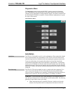
Ear Attachment for Rack Mounting (this image shows a 1RU device)
USE COVER SCREWS
4. Repeat procedure (steps 1 through 3) to attach the remaining ear to the
opposite side.
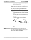
Stacking
Four “feet” are provided with the TPS-GA-TPI so that if the unit is not rack
mounted, the rubber feet can provide stability when the unit is placed on a flat
surface or stacked. These feet should be attached prior to the hookup procedure by
removing the adhesive backing and pressing them onto the bottom of the device.
Refer to the following illustration for placement of the feet.