


Crestron TPS-GA-TPI Isys
®
G-Series Touchpanel Interface
Operations Guide – DOC. 6501 Isys
®
G-Series Touchpanel Interface: TPS-GA-TPI • 31
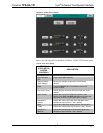
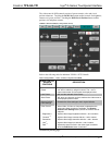
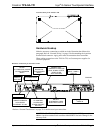
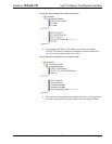
Foot Placement for the TPS-GA-TPI
PLACE FEET IN CORNERS
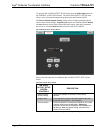
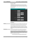
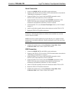
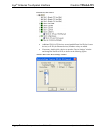
Hardware Hookup
Make the necessary connections as called out in the illustration that follows this
paragraph. Refer to “Network Wiring” on page 12 before attaching the 4-position
terminal block connector. Apply power after all connections have been made.
When making connections to the TPS-GA-TPI, use Crestron power supplies for
Crestron equipment.
Hardware Connections for the TPS-GA-TPI
HEADPHONES
RS-232:
TO COMPUTER, MOUSE
OR TOUCHSCREEN
INPUT*
USB:
MOUSE OR
TOUCHSCREEN
INPUT*
LAN:
10BaseT/100BaseTX
HIGH SPEED
ETHERNET TO LAN
NET:
TO CONTROL
SYSTEM AND
OTHER CRESNET
DEVICES
QM OUT:
QUICKMEDIA VIDEO
AND AUDIO OUTPUT
RGBHV
OUTPUT:
VIDEO OUT
RGBHV
INPUT 1 AND 2:
VIDEO IN
Y, P
b
/Y, P
r
/C/COMP:
VIDEO IN
GROUND
MEMORY EXP:
COMPACT FLASH AND
DUAL PCMCIA SLOTS
(FOR FUTURE
APPLICATIONS)
24VDC:
AC POWER PACK
* Refer to “External Touchscreen” on page 32 for touchscreen input connections.
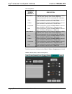
CAUTION: The TPS-GA-TPI can be powered by either the 24VDC power jack
OR the 4-position terminal block connector labeled NET. Not both. Damage to the
unit may result.