CY7C601xx, CY7C602xx
Document 38-16016 Rev. *E Page 4 of 68
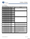
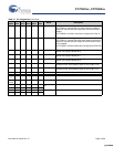
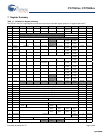
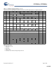
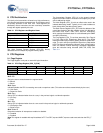
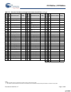
6.1 Pin Assignments
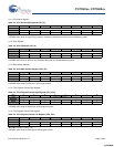
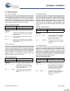
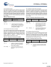
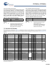
Table 6-1. Pin Assignments
48
SSOP
40
PDIP
28
SSOP
24
QSOP
24
SOIC
24
PDIP
Name Description
7 3 P4.0 GPIO Port 4—configured as a group (nibble)
62 P4.1
42 38 P4.2
43 39 P4.3
34 30 19 18 1 P3.0 GPIO Port 3—configured as a group (byte)
35 31 20 19 2 P3.1
36 32 P3.2
37 33 P3.3
38 34 24 P3.4
39 35 25 P3.5
40 36 26 P3.6
41 37 27 P3.7
15 11 11 11 18 P2.0 GPIO Port 2—configured as a group (byte)
14 10 10 10 17 P2.1
13 9 P2.2
12 8 P2.3
11 7 5 P2.4
10 6 4 P2.5
953 P2.6
842 P2.7
25 21 15 14 13 20 P1.0 GPIO Port 1 bit 0
If this pin is used as a general purpose output it draws current.
It is, therefore, configured as an input to reduce current draw.
26 22 16 15 14 21 P1.1 GPIO Port 1 bit 1
If this pin is used as a general purpose output it draws current.
It is, therefore, configured as an input to reduce current draw.
28 24 18 17 16 23 P1.2 GPIO Port 1 bit 2
29 25 19 18 17 24 P1.3/SSEL GPIO Port 1 bit 3—Configured individually
Alternate function is SSEL signal of the SPI bus.
30 26 20 21 20 3 P1.4/SCLK GPIO Port 1 bit 4—Configured individually
Alternate function is SCLK signal of the SPI bus.
31 27 21 22 21 4 P1.5/SMOSI GPIO Port 1 bit 5—Configured individually
Alternate function is SMOSI signal of the SPI bus.
32 28 22 23 22 5 P1.6/SMISO GPIO Port 1 bit 6—Configured individually
Alternate function is SMISO signal of the SPI bus.
33 29 23 24 23 6 P1.7 GPIO Port 1 bit 7—Configured individually
TTL voltage threshold.
[+] Feedback [+] Feedback


