


DIP Switch Settings and Connectors 125
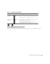
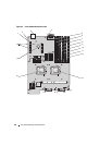
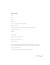
Table 6-2. System Board Connectors
Connector Description
1 PASSWD
(switch 1)
password switch 1
2 NVRAM_CLR
(switch 2)
clear NVRAM switch 2
3 CON2 Midplane connectors 2
4 CON1 Midplane connectors 1
5 DIMM 1 Memory module connector, slot 1
6 DIMM 5 Memory module connector, slot 5
7 DIMM 2 Memory module connector, slot 2
8 DIMM 6 Memory module connector, slot 6
9 DIMM 3 Memory module connector, slot 3
10 DIMM 7 Memory module connector, slot 7
11 DIMM 4 Memory module connector, slot 4
12 DIMM 8 Memory module connector, slot 8
13 CPU1 Processor 1 connector
14 CTRL_PNL Front control panel cable connector
15 SAS_0 Hard drive 0 connector
16 TOE_KEY Hardware key socket for enabling the integrated NIC TOE feature
17 SAS_1 Hard drive 1 connector
18 CPU2 Processor 2 connector
19 BATTERY Connector for the 3.0-V coin battery
20 J7039, J7040 Daughter card connectors
NOTE: For the full name of an abbreviation or acronym used in this table, see the "Glossary" on page 149.