


84 Installing System Options
3
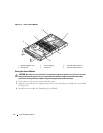
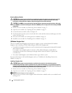
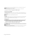
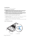
Remove the three screws that secure the daughter card to the server module board. See Figure 3-17.
NOTICE: Hold the daughter card by its edges only.
4
Lift up the daughter card from its connector and remove it from the server module board.
5
Close the server module. See "Closing the Server Module" on page 76.
6
Install the server module. See "Installing a Server Module" on page 74.
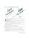
Activating the Integrated NIC TOE
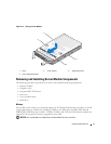
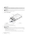
To add TOE functionality to the server module’s integrated NIC, install the TOE NIC hardware key in
the TOE_KEY socket on the system board (
see Figure 6-3.) Both single-port and dual-port TOE hardware
keys are available.
NOTICE: In a NIC team, a dual-port TOE hardware key is required.
Processors
It is possible to upgrade your processor(s) to take advantage of future options in speed and functionality.
Each processor and its associated internal cache memory are contained in a land grid array (LGA)
package that is installed in a ZIF socket on the system board.
Removing a Processor
CAUTION: Only trained service technicians are authorized to remove the system cover and access any of the
components inside the system. See your Product Information Guide for complete information about safety
precautions, working inside the computer, and protecting against electrostatic discharge.
1
Remove the server module. See "Removing a Server Module" on page 73.
2
Open the server module. See "Opening the Server Module" on page 75.
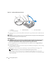
CAUTION: The processor and heat sink can become extremely hot. Be sure the processor has had sufficient time
to cool before handling.
NOTICE: Never remove the heat sink from a processor unless you intend to remove the processor. The heat sink is
necessary to maintain proper thermal conditions.
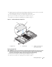
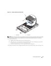
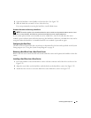
3
Loosen the four screws that secure the heat sink to the server module board. See Figure 3-18.