Properties
Subtabs: Health | Information | System Components (FRU) | Front Panel
Under the Properties tab, you can:
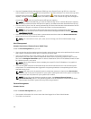
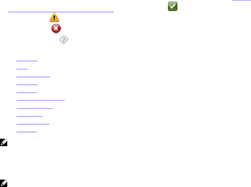
• View the health or status of hardware components and sensors. Each listed component has a System/
Server Module Component Status Indicators icon next to its name. indicates that a component is
healthy (normal). indicates that a component has a warning (noncritical) condition and requires
prompt attention. indicates that a component has a failure (critical) condition and requires
immediate attention. indicates that a component's health status is unknown. The available
monitored components include:
– Batteries
– Fans
– Hardware Log
– Intrusion
– Network
– Power Management
– Power Supplies
– Processors
– Temperatures
– Voltages
NOTE: Batteries is supported only on Dell PowerEdge 10G systems. The Power supplies is not
available on Dell PowerEdge 1900.
Power Management is supported on limited Dell PowerEdge
10G systems. Power Supply Monitoring and Power Monitoring features are available only for
systems that have two or more redundant, hot-swappable power supplies installed. These features
are unavailable for permanently installed, non-redundant power supplies that lack power
management circuitry.
NOTE: If the QLogic QLE2460 4Gb Single-Port Fibre Channel HBA, QLogic QLE2462 4Gb Dual-
Port Fibre Channel HBA, Qlogic QLE2562 Dual Port FC8 Adapter, or Qlogic QLE2560 Single Port
FC8 Adapter cards are installed on 12G systems, the System Components (FRU) screen is not
displayed.
• View information about the main system chassis attributes such as the Host Name, iDRAC version,
Lifecycle Controller version, Chassis Model, Chassis Lock, Chassis Service Tag, Express Service Code,
and Chassis Asset Tag. The Express Service Code (ESC) attribute is a 11-digit numeric-only conversion
of the Dell system Service Tag. When calling Dell Technical Support, you can key in the ESC for auto
call routing.
• View detailed information about the field-replaceable units (FRUs) installed in your system (under the
System Components (FRU) sub tab).
• Enable or disable the managed system's front panel buttons, namely Power button and Non-Masking
Interrupt (NMI) button (if present on the system). Also, select the managed system’s LCD Security
Access level. The managed system’s LCD information can be selected from the drop-down menu.
You can also enable Indication of Remote KVM session from the Front Panel sub tab.
Batteries
Click the Batteries object to view information about your system’s installed batteries. Batteries maintain
the time and date when your system is turned off. The battery saves the system’s BIOS setup
48


