


Dell
™
Latitude™ E6400 XFR Service Manual
Page 36
NOTE: If a new processor is installed, you will receive a new thermal grease kit along with a tech
sheet to illustrate proper installation.
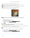
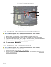
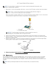
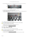
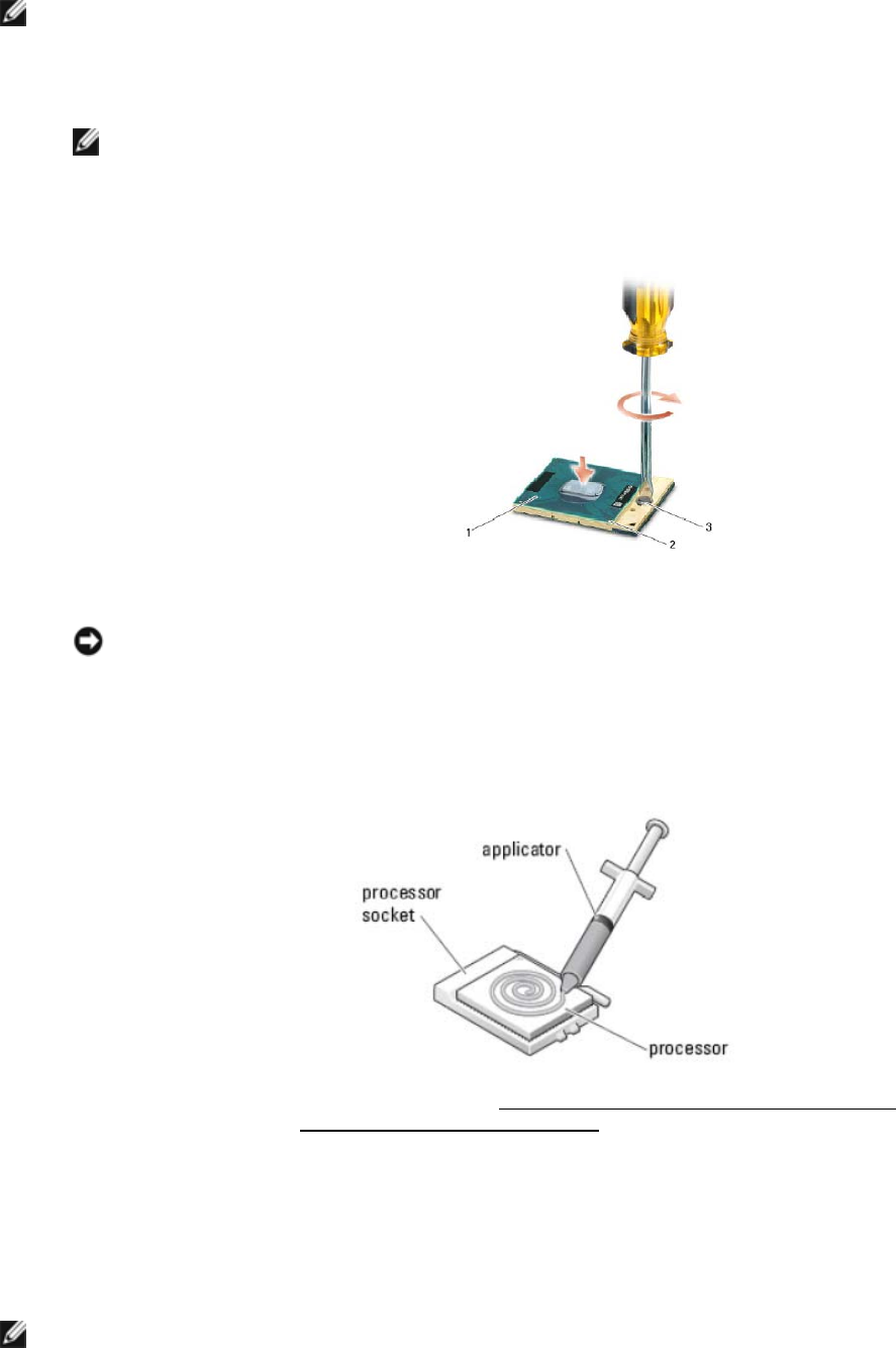
1. Align the pin-1 corner of the processor with the pin-1 corner of the ZIF socket, and then insert the processor.
NOTE: The pin-1 corner of the processor has a triangle that aligns with the triangle on
the pin-1 corner of the ZIF socket, then insert the processor.
When the processor is properly seated, all four corners are aligned at the same height. If one or more corners
of the processor are higher than the others, the processor is not seated properly.
1 ZIF socket 2 Pin-1 corner
3 ZIF-socket cam screw
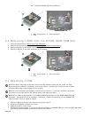
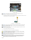
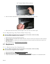
NOTICE: To avoid damage to the processor, hold the screwdriver so that it is
perpendicular to the processor when turning the cam screw.
2. Tighten the ZIF socket by turning the cam screw clockwise to secure the processor to the system board.
3. Clean the heatsink. Use the cleaning pad provided with the processor kit to remove any old thermal grease
between the 3 captive screws.
4. Apply the thermal grease. Follow the instructions provided with the processor kit, use the syringe to apply
thermal grease in a spiral pattern to the processor thermal-cooling assembly.
5. Replace the processor heatsink assembly (see Replacing the Processor Heatsink Assembly
).
6. Follow the procedures in After Working on Your Computer.
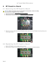
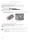
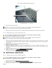
13 Memory
Your computer has two user-accessible SODIMM sockets. You can increase your computer memory by installing
memory modules on the system board. See "Specifications" in your Setup and Features Information Guide for
information on the memory supported by your computer. Install only memory modules that are intended for your
computer.
NOTE: Memory modules purchased from Dell are covered under your computer warranty.