


Dell
™
Latitude™ E6400 XFR Service Manual
Page 62
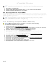
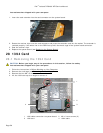
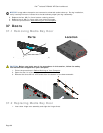
8. Remove the I/O card.
31.2 Replacing the I/O Card
1. Replace the I/O card.
2. Replace the sniffer card bracket.
3. Replace the sniffer card (see Replacing the Wi-Fi Sniffer Card
).
4. Replace the M2.5 x 5-mm screw from the I/O card.
5. Replace the RJ-11 modem connector (See Replacing the RJ-11 Modem Connector
).
6. Replace the modem (see Replacing the Modem).
7. Replace the system board (see Replacing the System Board Assembly
).
8. Follow the procedure for After Working on Your Computer
.
32 RJ-11 Modem Connector
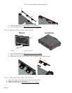
32.1 Removing the RJ-11 Modem Connector
CAUTION: Before you begin any of the procedures in this section, follow the safety
instructions that shipped with your computer.
1. Follow the procedures in Before Working on Your Computer
.
2. Remove the bottom access panel, LCD cable channel covers, display assembly, led cover, palm rest overlay,
keyboard and palm rest (see Removing the Palm Rest
).
3. Remove the modem (see Removing the Modem
).
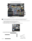
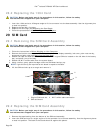
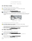
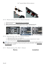
4. Pry up the RJ-11 modem connector to release the double-stick adhesive tape on the bottom of the connector,
and then lift the RJ-11 modem connector out of the base assembly.
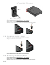
32.2 Replacing the RJ-11 Modem Connector
CAUTION: Before you begin any of the procedures in this section, follow the safety
instructions that shipped with your computer.
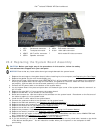
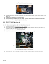
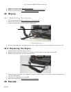
1. Place the RJ-11 modem connector into the base assembly, aligning the guides on the connector sides with the
base. Once installed, press down firmly on top of the RJ-11 connector to seal the adhesive to the base.
2. Replace the modem (see Replacing the Modem
).
3. Replace the palm rest, keyboard, palm rest overlay, led cover, display assembly, LCD cable channel covers
and bottom access panel (see Replacing the Palm Rest
).
4. Follow the procedures in After Working on Your Computer
.
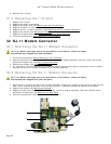
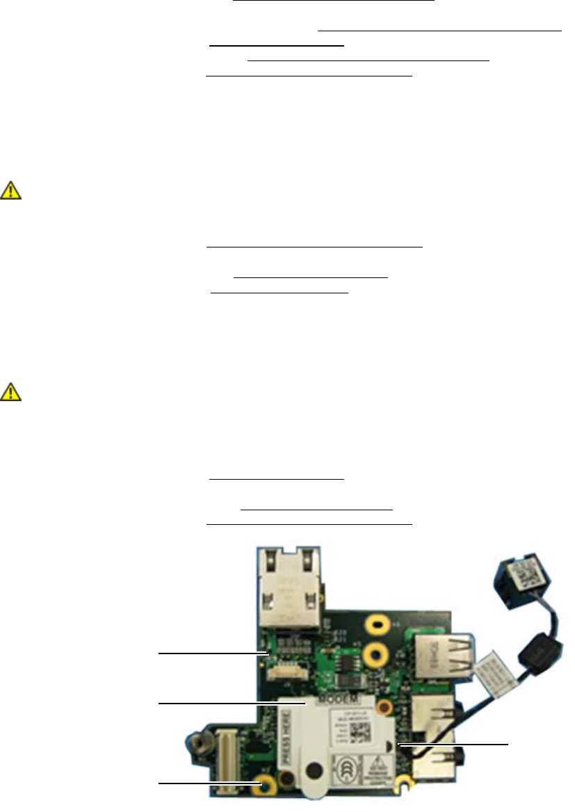
1 I/O card 2 RJ-11 modem card
1
2
3
4