


Dell
™
Latitude™ E6400 XFR Service Manual
Page 54
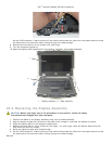
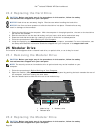
NOTE: The security screw on the modular drive is optional and may not be installed on your computer.
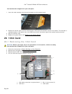
1. Slide the drive in the modular bay.
2. Close the modular (XBay) disk drive door by rotating it up until it clicks into its locked position.
3. Follow the procedures in After Working on Your Computer
.
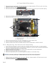
26 System Board Assembly
The system board’s BIOS chip contains the Service Tag, which is also visible on a barcode label on the bottom of the
computer. The replacement kit for the system board includes media that provides a utility for transferring the Service
Tag to the replacement system board.
NOTE: The replacement kit for the system board also includes media that provides a utility to set the
system board as XFR, and a tech sheet for running this utility.
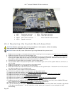
26.1 Removing the System Board Assembly
CAUTION: Before you begin any of the procedures in this section, follow the safety
instructions that shipped with your computer.
1. Follow the instructions in Before Working on Your Computer
.
2. Remove the bottom access panel, LCD cable channel covers, display assembly, LED cover, palm rest overlay,
keyboard, and palm rest and smartcard assembly (see Removing the Palm Rest
).
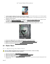
3. Remove the VGA panel cover (see Removing the VGA Panel Cover).
4. Remove the coin-cell battery (see Removing the Coin Cell Battery
).
5. Remove any mini-pci cards from the WWAN/FCM card slot, WLAN/WiMax card slot, and from the
WPAN/UWB/FCM card slot, if present (see Chapter 5, 6, 7 and 8
for removal procedures).
6. Remove the memory modules (see Removing a Memory Module
).
Remove the fan, processor heatsink assembly and processor (see Removing the Processor Module
).
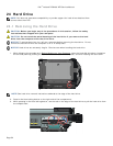
7. Remove the hard drive (see Removing the Hard Drive
).
8. Remove the modular drive (see Removing the Modular Drive).
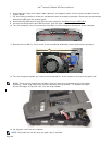
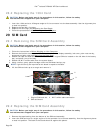
9. Disconnect the Wi-Fi sniffer cable from the system board.
10. Disconnect the SIM card assembly from the system board (see Removing the SIM Card Assembly
).
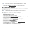
11. Disconnect the 1394 cable from the system board.
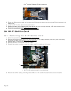
12. Disconnect the smartcard ribbon cable from the system board.
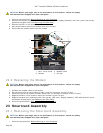
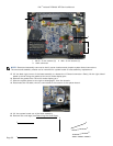
13. Remove the two M2 x 3-mm screws that secure the card cage to the chassis.
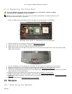
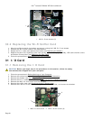
14. Remove eight M2.5 x 5-mm screws from the system board.