


Dell
™
Latitude™ E6400 XFR Service Manual
Page 46
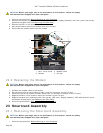
On the LVDS connector, rotate the blue pull-tab used to disconnect the cable from the system board to wrap
the cable-side of the connector when routing through the chassis bridge.
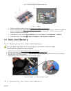
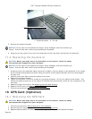
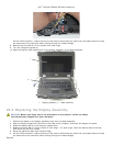
8. Remove the three M2.5 x 8-mm screws from each hinge.
9. Turn the computer topside up.
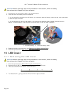
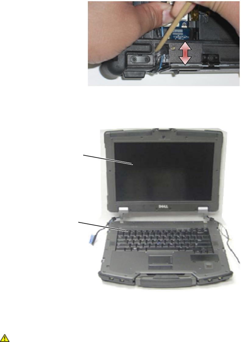
10. Open the display to 90 degrees and lift the display assembly off the base assembly.
1 Display assembly 2 Base assembly
20.2 Replacing the Display Assembly
CAUTION: Before you begin any of the procedures in this section, follow the safety
instructions that shipped with your computer.
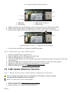
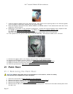
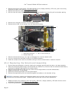
1. Position the cables on the display assembly away from the base assembly.
2. Align the display hinges with the holes in the base of the computer, and lower the display into place.
3. Close the display and turn the computer upside down.
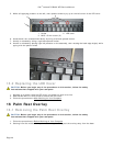
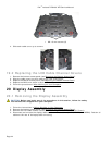
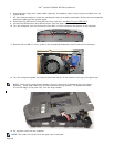
4. Replace the three M2.5 x 8-mm screws on each hinge. For each hinge, install the bottom side screw first,
then install the two rear screws.
5. Route the cables through each chassis bridge.
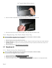
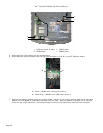
6. On the LVDS connector, rotate the blue pull-tab used to disconnect the cable from the system board to wrap
the cable-side of the connector when routing through the chassis bridge.
1
2