


Dell
™
Latitude™ E6400 XFR Service Manual
Page 55
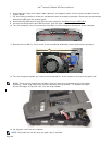
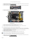
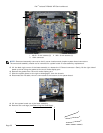
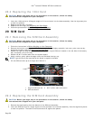
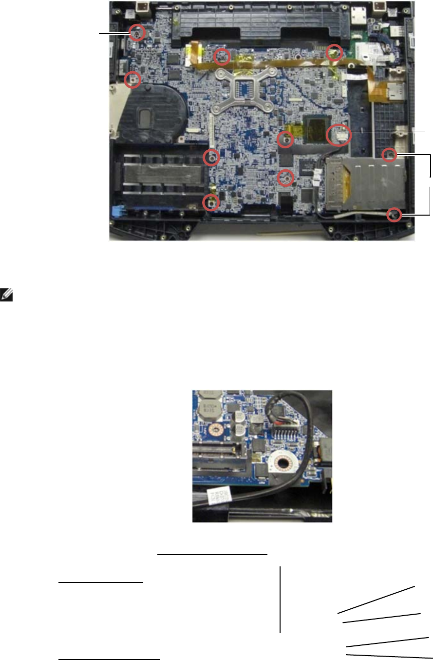
1 M2.5 x 5-mm screws (8) 2 M2 x 3-mm screws (2)
3 1394 connector
NOTE: Smartcard assembly removed to clarify screw locations and pinpoint system board connectors.
The smartcard assembly should not be removed for system board or base assembly replacement.
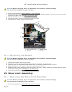
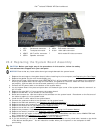
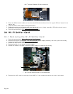
15. Lift the back-right corner of the base assembly to release the I/O board connector. Gently lift the right side of
board up while lifting the gasket at the multi-mode display port.
16. Remove the gasket from the multi-mode display port.
17. Slide the system board to the right to disengage it from the chassis.
18. Disconnect the DC cable, which is connected to the bottom of the system board.
19. Lift the system board out of the base assembly.
20. Remove the card cage (see Removing the Card Cage
).
1
2
3
4
5
6
7
2
3
1