


7-12
'HOO2SWL3OH[*;*;S0DQDJHG3&DQG2SWL3OH[1;1HW3&6\VWHPV6HUYLFH0DQXDO
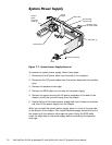
6\VWHP%RDUG
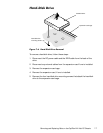
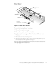
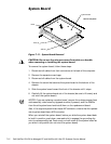
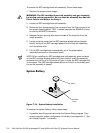
)LJ XUH6\VWHP%RDUG5HPRYDO
&$87,21'RQRWXVHWKHPLFURSURFHVVRUKHDWVLQNDVDKDQGOH
ZKHQUHPRYLQJRULQV WDOOLQJWKHV\VWHPERDUG
To remove the system board, follow these steps:
1. Disconnect all cables from their connectors at the back of the computer.
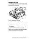
2. Remove the expansion-card cage.
3. Disconnect all cables from the system board.
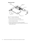
4. Remove the screw that secures the system board to the bottom of the
chassis.
5. Slide the system board toward the front of the chassis until it stops.
6. Carefully lift the system board out of the chassis (be sure to lift evenly and
not twist the system board).
NOTES: If you are replacing a system board, remove the microprocessor/heat
sink assembly, video-memory upgrade module (if present), and the DIMMs
from the old system board and install them on the replacement board.
Also, if the original system board has a NIC connector, ensure that the replace-
ment system board has a NIC connector.
When you reinstall the system board, before you slide the system board back
to lock it in position, push down near each slot to engage the grounding clip
onto its corresponding tab. Push evenly on both sides of the system board as
you slide it into position (do not twist the system board).
screw
slots (5)
tabs (5)
back of computer
system board