


System Overview 1-25
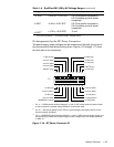
3 LQ$VV LJQPHQWVI RUWK H'&3RZHU &RQ QHFWRUV
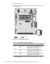
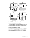
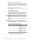
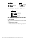
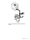
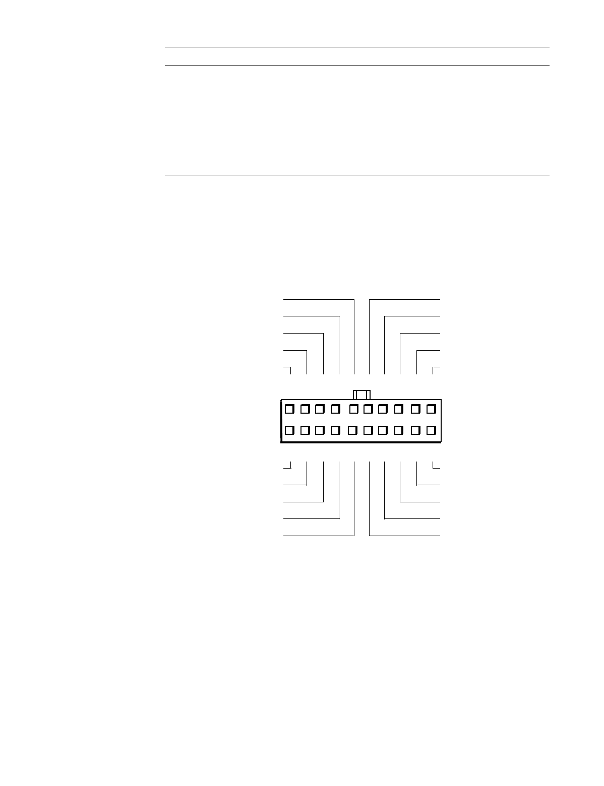
The power-supply output voltages can be measured at the back (wire side) of
the connectors without disconnecting them. Figures 1-15 through 1-17 show
the wire side of the connectors.
1
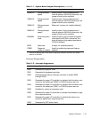
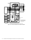
Pin 11 — PSON# should measure between +4 and +5 VDC except when the power button
on the front panel is pressed, taking PSON# to its active-low state.
2
Pin 19 — Thermal fan-speed control (TFSC) is a power-supply input signal used to control
the power-supply fan speed.
3
Pin 5 — PWRGOOD should measure between +4 and +5 VDC when the power supply is on
and operating to indicate that all power-supply output voltages are within ranges specified
in Table 1-4.
)LJXUH'&3RZHU&RQQHFWRU3
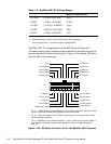
–12 VDC –10.80 to –13.20 VDC 0.3 A (low-profile computers);
0.3 A (midsize and mini tower
computers)
–5 VDC –4.50 to –5.50 VDC 0.3 A (low-profile computers);
0.3 A (midsize and mini tower
computers)
+5 VFP
3
+4.75 to +5.25 VDC 10 mA
3
VFP (volts flea power) — sometimes called “standby power.”
7DEOH2SWL3OH[*;*;S'&9ROWDJH5DQJHV
FR QW LQXH G
9ROWDJH 5DQJH 0D[L P XP 2X WS XW &XU UH QW
11
1
PWRGOOD
3
(orange)
–12 VDC (blue)
+12 VDC (yellow)
+5 VFP (purple)
common (black)
234 5678 910
12 13 14 15 16 17 18 19 20
3
+5 VDC (red)
+5 VDC (red)
+5 VDC (red)
+5 VDC (red)
+5 VDC (red)
+5 VDC (red)
common (black)
common (black)
common (black)
PSON#
1
(gray)
common (black)
common (black)
common (black)
–5 VDC (white)
TFSC
2
(brown)