1-6
'HOO2SWL3OH[*;*;S0DQDJHG3&DQG2SWL3OH[1;1HW3&6\VWHPV6HUYLFH0DQXDO
$7,0XOWLPHGLD&KDQQHO
The ATI multimedia channel (AMC) implements a local graphics bus that allows
external devices to attach directly to the graphics controller. The AMC allows
devices to transfer video stream data to the graphics controller, for example,
MPEG-2 decoding for digital video disk (DVD) applications, or to receive video
stream data from the graphics controller to the device, for example, TV-Out
circuitry, or to do both simultaneously. Most of the video stream data trans-
fers occur on the AMC without congesting the PCI bus bandwidth.
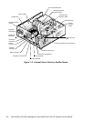
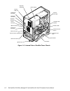
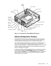
The 40-pin AMC connector, shown in Figure 1-12, consists of three ports into
the graphics controller: a digital video stream (DVS) port for video input into the
graphics controller, a multimedia peripheral port (MPP) for video input and out-
put from the graphic controller, and an inter-integrated circuit (I
2
C)-compatible
serial control port for controlling the attached devices. A fourth port, audio
mixing bus (AMB), is not supported by the system. To route mixed audio from
an AMC-compliant adapter card to the system board, CD-ROM audio cables
must be attached from the adapter card’s CD-ROM audio input and CD-ROM
audio output connections to the AMC connector. See the AMC-compliant
adapter card’s documentation for more information.
7HOHSKRQ\$SSOLFDWLRQ3 URJUDPPLQJ,QWHUIDFH
The OptiPlex GX1/GX1p and OptiPlex NX1 systems include a telephony appli-
cation programming interface (TAPI) that allows the system board audio to
interface with a modem to facilitate speakerphone functionality. The TAPI-
compliant telephony input is a mono source with a maximum signal level of
2Vrms.
&KDVVLV,QWUXVLRQ'HWHFWLRQ
Chassis Intrusion displays the status of the system chassis intrusion monitor.
The settings for this option are Enabled, Enabled-Silent, or Disabled. The
default is Enabled.
If the computer cover is removed while the intrusion monitor is set to
Enabled, the setting changes to Detected, and the following message
appears during the boot sequence at the next system start-up:
$OHUW&RYHUZDVSUHYLRXVO\UHPRYHG
If the computer cover is removed while the intrusion monitor is set to
Enabled-Silent, the setting changes to Detected, but the alert message is not
displayed during the boot sequence at the next system start-up.
If the intrusion monitor is set to Disabled, no intrusion monitoring occurs and
no messages are displayed.
To reset the Detected setting, enter the System Setup program during the
system’s POST. Highlight the Chassis Intrusion option and press the left- or
right-arrow key to choose Enabled, Enabled-Silent, or Disabled.
NOTE: If a setup password has been assigned by someone else, contact your
network administrator for information on resetting the chassis intrusion detector.


