


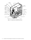
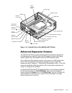

System Overview 1-7
,QWHJUDWHG(WKHUQHW1,&6XSSRUW2SWLRQDO
The OptiPlex GX1 systems and OptiPlex NX1 systems are available with or
without an integrated Ethernet NIC subsystem. The OptiPlex GX1p systems
are available only with an integrated Ethernet NIC subsystem.
The integrated 10/100-Mbps 3Com
®
PCI 3C905B-TX Ethernet NIC subsystem
supports the Wakeup On LAN feature and the 10BASE-T and 100BASE-T stan-
dards. The NIC subsystem connects to the Ethernet network through a single
RJ45 connector on the back of the computer. The RJ45 connector and the NIC
interface circuitry are mounted on the system board.
The NIC connector on the computer’s back panel has the following indicators:
A yellow
activity indicator
flashes when the system is transmitting or
receiving network data. (A high volume of network traffic may make this
indicator appear to be in a steady “on” state.)
A green
link integrity indicator
lights up when there is a good connection
between the network and the NIC. When the green indicator is off, the
system is not detecting a physical connection to the network.
1HWZRUN&DEOH5HTXLUHPHQWV
The computer’s NIC connector (RJ45) is designed for attaching to an
unshielded twisted pair (UTP) Ethernet cable. The other end of the cable con-
nects to an RJ45 jack wall plate or to an RJ45 port on a UTP concentrator or
hub, depending on the network configuration.
Chapter 4, “Using Integrated Devices,” in the
Reference and Installation Guide
provides instructions for connecting the computer to, and configuring it for use
on, an Ethernet network. For OptiPlex NX1 systems, refer to the online
Net-
work Administrator’s Guide.
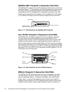
)XOO6HWRI,23RUWV
For desktop connectivity, the OptiPlex GX1/GX1p and OptiPlex NX1 systems
include the following ports:
25-hole, bidirectional parallel port with EPP/ECP and demand-mode DMA
support
Two Universal Serial Bus (USB) ports
Two 9-pin serial ports
Two PS/2 ports (mouse and keyboard)
One 15-hole video connector
Three audio jacks (microphone, line-in, and line-out)
One RJ45 Ethernet NIC connector
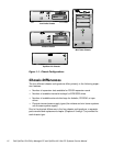
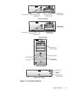
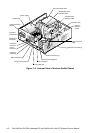
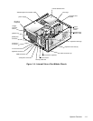
See Figures 1-3 through 1-6 for I/O port identifiers for the various chassis
configurations.