


1-26
'HOO2SWL3OH[*;*;S0DQDJHG3&DQG2SWL3OH[1;1HW3&6\VWHPV6HUYLFH0DQXDO
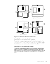
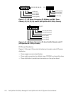
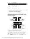
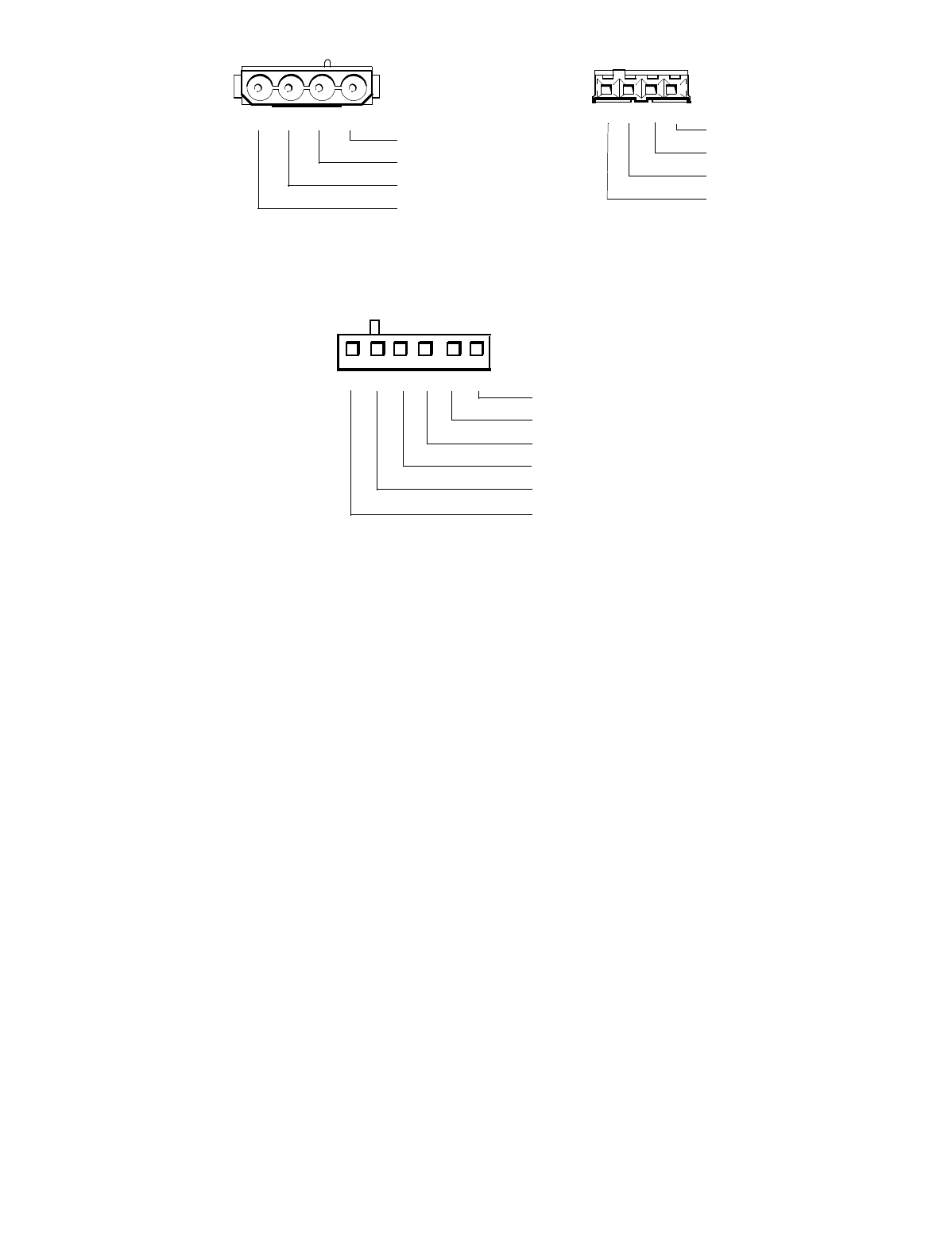
)LJ X UH'&3RZHU&RQQHFWRUV30LGVL]HDQG0LQL7RZHU
&KDVVLV3333DQG3$OO2SWL3OH[*;*;S&KDVVLV
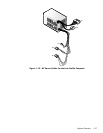
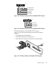
)LJXUH'&3RZHU&RQQHFWRUV3/RZ3URILOH&KDVVLVDQG3
$OO2SWL3OH[*;*;S&KDVVLV
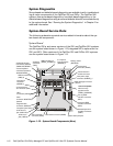
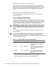
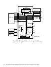
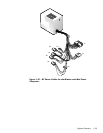
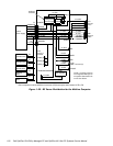
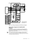
'&3RZHU'LVWULEXWLRQ
Figures 1-19 through 1-23 provide the following information about DC power
distribution:
Power-supply connector identification
Power cable connections for diskette, tape, CD-ROM, and hard-disk drives
Power distribution to sockets and connectors on the system board
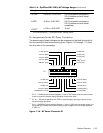
1234
+5 VDC (red)
common (black)
common (black)
+12 VDC (yellow)
1234
+5 VDC (red)
common (black)
common (black)
+12 VDC (yellow)
P2, P3, P5, P6, P9
P4
1234
+3.3 VDC (blue/white)
common (black)
common (black)
5
P2, P7
6
+3.3 VDC (blue/white)
+3.3 VDC (blue/white)
common (black)