


4-20
'HOO2SWL3OH[*;*;S0DQDJHG3&DQG2SWL3OH[1;1HW3&6\VWHPV6HUYLFH0DQXDO
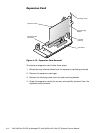
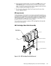
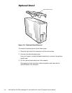
To remove the SEC cartridge/heat sink assembly, follow these steps:
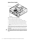
1. Remove the system power supply.
:$51,1*7KH6(&FDUWULGJHKHDWVLQNDVVHPEO\FDQJHWH[WUHPHO\
KRWGXULQJV\VWHPRSHUDWLRQV%HVXUHWKDWWKHDVVHPEO\KDVKDGVXI
ILFLHQWWLPHWRFRROEHIRUHWRXFKLQJLW
2. Locate the SEC cartridge/heat sink assembly.
3. Disconnect the microprocessor fan connector from the 3-pin connector on
the system board (labeled “FAN”), located between the SERIAL2 connec-
tor and the MONITOR connector.
4. Release the two securing clips near the base of the heat sink from the
metal standoffs.
5. Locate and press inward on the SEC cartridge release latches (located
directly on top of the SEC cartridge adjacent to the heat sink assembly)
until the latches click.
6. Lift the SEC cartridge/heat sink assembly out of its guide bracket
assembly/connector on the system board.
NOTE: When installing the SEC cartridge/heat sink assembly, press outward
on the SEC cartridge release latches and then carefully orient the assembly
and press firmly with up to 25 pounds of force to mate the SEC cartridge with
its connector. The SEC cartridge release latches will click into the locked posi-
tion as the assembly is seated.
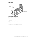
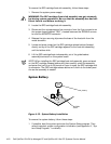
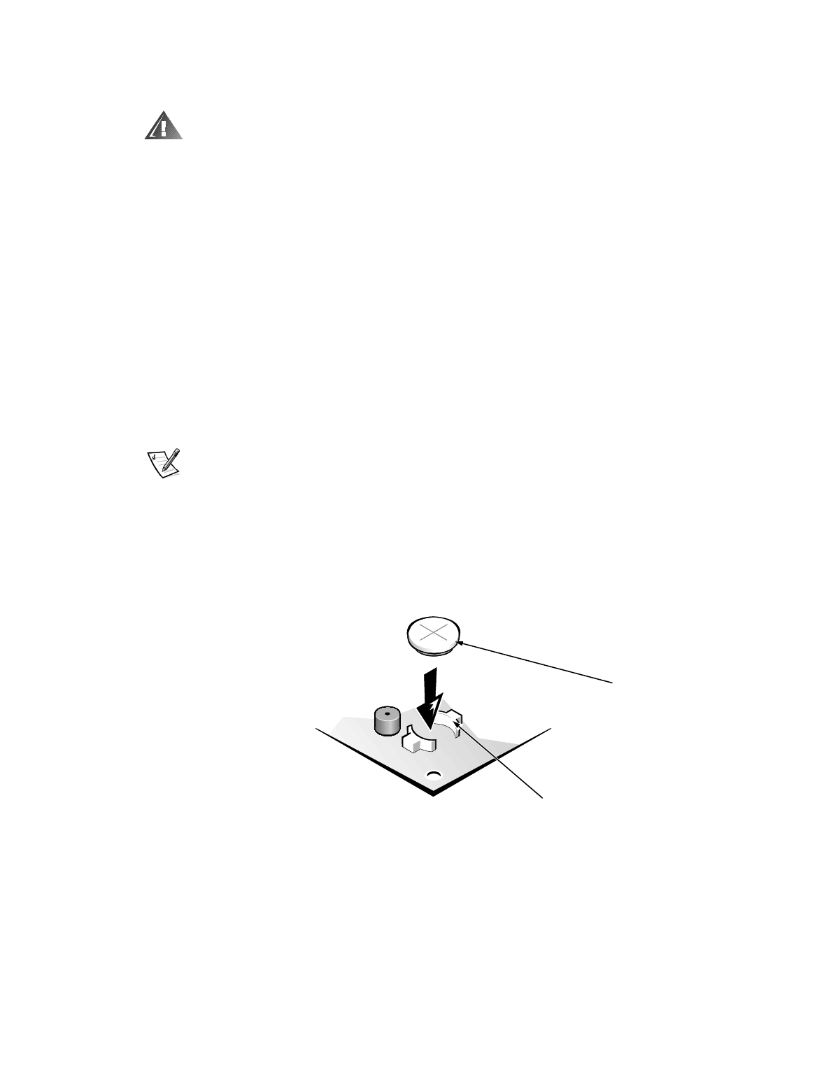
6\VWHP%DWWHU\
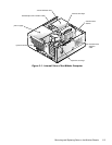
)LJXUH 6\VWHP%DWWHU\, QV WDOODWLRQ
To remove the system battery, follow these steps:
1. If possible, boot the system and enter the System Setup program. Then
record important system configuration information (see Appendix A, “Sys-
tem Setup Program,” for details).
BATTERY
socket
battery