856 Configuring L2 Multicast Features
3
A forwarding entry is created by D3 for VLAN20, 239.20.30.42 – 1/0/6,
1/0/20.
4
Client D will receive the multicast stream from Server B because it is
forwarded by D1 to D3 and then to D4 because D4 is a multicast router.
Because the multicast stream is present on D3, a L2 forwarding entry is
created on D3, where 239.20.30.42 is not a registered group.
5
Client F does not receive the multicast stream because it did not respond
to queries from D4.
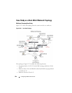
Snooping Switch Interaction with a Multicast Router
In the example network topology, consider Client B and Server A. Both are in
the same subnet VLAN10
–
192.168.10.70/24. Server A is a source for
multicast stream 239.20.30.40. D4 sends periodic queries on VLAN 10 and
VLAN 20, and these queries reach D1, D2, and D3 via trunk links, which in
turn forward them in VLAN 10 and VLAN 20 to reach their respective
attached clients. PIM-SM is enabled and IGMP snooping is disabled on
router D4, and IGMP snooping is enabled on D1, D2, and D3.
Multicast Source and Listener directly connected to Multicast Router on the
same routing VLAN: Server A Client B
1
Because multicast routing is enabled on D4 VLAN 10, an IP multicast
table entry is created to include D4 – 1/0/15, D4 – 1/0/20 as part of the L2
forwarding list members.
2
Client B sends a report for 239.20.30.40.
3
The IP multicast table entry is modified to include only D4 – 1/0/15 as the
layer 2 forwarding list member.
4
Client B receives multicast data.
5
The multicast stream is not forwarded to D3 on trunk link 1/0/20 because
no other clients requested this data.
Multicast Source directly connected to Multicast Router, and Listener
connected to a different routing VLAN via intermediate snooping switches:
Server A Client F
Clients A, D and F are in the same subnet VLAN20 - 192.168.20.70/24. Server
A is in a different subnet VLAN10
–
192.168.10.70/24.
1
Client F sends a report for 239.20.30.40.


