Configuring L2 Multicast Features 857
2
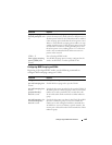
A multicast forwarding entry is created on D2 VLAN20, 239.20.30.40 –
1/0/20, PortChannel1.
3
The Client F report message is forwarded to D3-PortChannel1 (multicast
router attached port).
4
A multicast forwarding entry is created on D3 VLAN 20, 239.20.30.40 –
PortChannel1, 1/0/20.
5
The Client F report message is forwarded to D4 via D3 – 1/0/20 (multicast
router attached port).
6
An IP multicast routing entry is created on D4 VLAN 10 – VLAN 20 with
the L3 outgoing port list as VLAN 20 – 1/0/20.
7
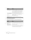
The multicast stream is routed to D3.
8
The multicast stream is forwarded to listener Client F using forwarding
entries created on D3 and D2.
9
Clients A and D do not receive the Server A multicast stream because they
did not send a report.
Multicast Source connected to Multicast Router via intermediate snooping
switches, and Listener directly connected to multicast router in a different
routing interface: Server B Client B
Server A and Clients B, C, and E are on the same subnet
VLAN10
–
192.168.10.70/24. Server B is in a different subnet
VLAN20
–
192.168.20.70/24.
1
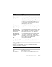
Client B sends a report for 239.20.30.42.
2
Multicast Router D4 learns group 239.20.30.42.
3
The administrator creates a static multicast forwarding entry on D1
VLAN 20, 239.20.30.42 – 1/0/15 and on D3 VLAN 20, 239.20.30.42 –
1/0/20.
4
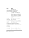
The multicast stream from Server B reaches D4 via trunk links because it is
a statically registered group on D1 and D3. D4 is a multicast router.
5
An IP multicast routing entry is created on D4 VLAN 20 – VLAN 10 with
the L3 outgoing port list as VLAN 10 – 1/0/15.
6
Client B receives multicast data from Server B.
7
Server A and Clients C and E do not receive Server B data because no
report messages were sent requesting Server B traffic.


