


Hardware Installation 17
Daisy Chain Example
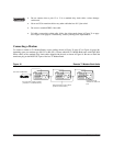
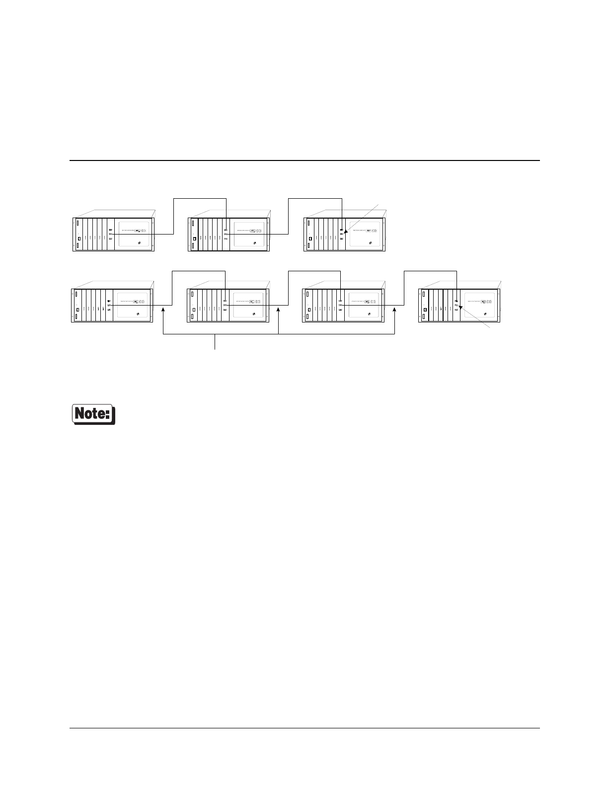
While setting up daisy chains, refer to the example shown in Figure 9 and the directions that follow.
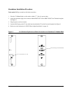
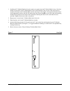
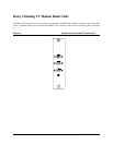
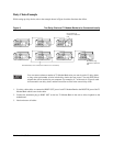
Figure 9 Two Daisy Chains of T1 Modem Banks to be Connected Locally
TM
TM TM TM TM
TMTM
7HUPLQDWRU SOXJ
LQVWDOOHG RQ +R VW 2XW
SRUW
7HUPLQ DWRU SOXJ
LQVWDOOH G RQ +RVW 2XW
SRUW
6WDQG DUG GDLV\ F KDLQ FDEOH ZLUH GLUHFW RU ZLUH GLUHFW
You can connect whatever number of T1 Modem Bank units you want in each of 2 daisy chains,
as long as the total number of units in both daisy chains does not exceed 7 for each EPC/X host
adapter that will be installed in your computer. For example, all 7 of the units in Figure 9 could
be connected in one daisy chain, and there would be no units in the second daisy chain.
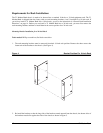
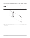
1. Use daisy chain cables to connect the HOST OUT port of each T1 Modem Bank to the HOST IN port of the T1
Modem Bank which is next in the chain.
2. Connect the terminator plug to HOST OUT on the last T1 Modem Bank in the rack to allow loopback to the
motherboard.
3. Label and secure all cables.