


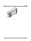


T1 Modem Bank
78
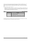
Alarms on a T1 Span
Alarm Reason for Alarm Result of Alarm
Red
Alarm
The T1 Modem Bank is not receiving a valid signal
from the T1 Line.
The T1 Modem Bank sends a “Yellow
Alarm” down the T1 line, and it will not
accept calls or dial out.
Yellow
Alarm
The Central Office was in a Red Alarm state (i.e., it
can’t hear you). The alarm goes away
approximately 15 seconds after the Red Alarm
clears itself.
The T1 Modem Bank can not accept
calls or dial out on the T1 line.
Blue
Alarm
Keep-alive signal from the T1 Line. Remote CSU is
generating it, or an improper supervision mode
(signaling) was chosen.
The T1 Modem Bank can not accept
calls or dial out on the T1 line.
T1 Modem Bank Interaction
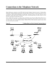
Interaction takes place between the PSTN, the T1 Modem Bank, and the PC containing the EPC/X host adapter.
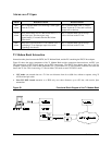
Figure 29 shows the major components of the T1 Modem Bank and the connections between them. An EPC sync
link interconnects an EPC/X host adapter and an EPC concentrator. (The EPC/X host adapter plugs into a slot in a
computer’s interface bus.) Data is then transmitted via V.34 modems to a T1 Line interface, which in turn sends the
data to the T1 line. This occurs using a T1 line in either CSU mode or non-CSU DSX-1 mode.
• CSU mode can transmit data on a T1 line over distances from 0 to 6,000 feet, without a repeater, using 22
AWG twisted-pair cable.
• Non-CSU DSX-1 mode transmits to a PBX only over short distances, up to 655 feet, with receive jitter
attenuation.
Figure 29 Functional Block Diagram of the T1 Modem Bank