


T1 Modem Bank
32
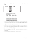
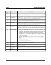
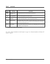
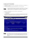
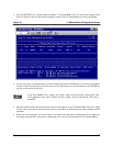
Table 5 Display Panel Status Codes
7 Segment
Display
Meaning Description
AC Activity
AC appears on the 7-segment display. The ten activity LEDs turn on sequentially from left to right.
The speed of this “chase light” display increases with the overall activity level of the T1 Modem
Bank.
LU Line Utilization
LU appears on the 7-segment display, and the ten LEDs become a bar graph indicating the
percentage (0-100%) of the time the synchronous communications line is being used.
PU Processor Utilization
PU appears on the 7-segment display, and the ten LEDs become a bar graph indicating the percentage
(0-100%) of the time the T1 Modem Bank’s microprocessor is being used.
PC Packet Count
PC appears on the 7-segment display, and the ten LEDs show a binary representation of the total
number of packets transmitted or received on the sync line between the EPC/X host adapter and the
T1 Modem Bank. Pressing both push-buttons simultaneously resets the count to 0.
EC Error Count
EC appears on the 7-segment display, and the ten LEDs show a binary representation of the total
number of errors counted on the sync line between the EPC/X host adapter and the T1 Modem Bank.
This indicates the quality of the line. Pressing both push-buttons simultaneously resets the count to 0
L1* T1 Line Card Status
L1 appears on the 7-segment display and corresponds to the vertically positioned text. LED
functions are as follows:
• for AMI/B8ZS, AMI is indicated when the LED is lit, B8ZS is indicated when the LED is unlit.
• for SF/ESF, SF is indicated when the LED is lit, ESF is indicated when the LED is unlit.
• for CSU/DSX-1, CSU is indicated when the LED is lit, DSX-1 is indicated when the LED is
unlit.
• The RED, BLUE and YELLOW LEDs will be lit if there is a red, blue, or yellow alarm
currently active on the T1 line.
• The LLOOP LED will be lit if the remote switch has placed the line card in local loopback
mode.
• The RLOOP LED will be lit if the remote switch has placed the line card in remote loopback
mode.
• D&I represents drop and insert.
• LOS indicates loss of signal from the T1 line.
ES* Errored Seconds
An Errored Second is a second with one or more Error Events
Cr* CRC Errors
A CRC error occurs when the CRC calculated by the T1 Modem Bank does not agree with the CRC
received from the network.
bS* Bursty Errored
Seconds
A Bursty Errored Second is a second with more than one, but less than 320 CRC errors.
EE* Error Events
A CRC error or a Loss Of Frame event