


vi T1 Modem Bank
List of Figures
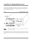
Figure 1 T1 Modem Bank Chassis, Front View.......................................................................................................1
Figure 2 Power Supply.............................................................................................................................................9
Figure 3 Line Card and Synchronous Cable Connections for Standalone T1 Modem Bank.................................11
Figure 4 Bracket Position For 19-inch Rack..........................................................................................................12
Figure 5 Bracket Position For 24-inch Rack..........................................................................................................13
Figure 6 T1 Modem Bank Unit Spacer..................................................................................................................14
Figure 7 Line Card .................................................................................................................................................15
Figure 8 Synchronous Ports and Terminal Port .....................................................................................................16
Figure 9 Two Daisy Chains of T1 Modem Banks to be Connected Locally .........................................................17
Figure 10 Remote T1 Modem Bank Units...............................................................................................................18
Figure 11 Mixing EPC Concentrators with T1 Modem Bank Units........................................................................19
Figure 12 DIP Switch Settings for I/O Port Address ...............................................................................................21
Figure 13 EPC/X Host Adapter Connected Locally to T1 Modem Banks ..............................................................25
Figure 14 Local and Remote T1 Modem Bank Units ..............................................................................................26
Figure 15 EPC/X Host Adapter Connected to Concentrators and T1 Modem Bank Units .....................................26
Figure 16 T1 Modem Bank Display Panel...............................................................................................................28
Figure 17 Main Screen.............................................................................................................................................36
Figure 18 T1 Modem Bank Configuration Screen...................................................................................................37
Figure 19 Line Card Status Display.........................................................................................................................42
Figure 20 Line Card Options Display ......................................................................................................................43
Figure 21 Modem Test Results ................................................................................................................................57
Figure 22 Line Card .................................................................................................................................................66
Figure 23 Modem Card ............................................................................................................................................69
Figure 24 Quick Manager Modem Revision Screen................................................................................................71
Figure 25 Power Supply...........................................................................................................................................74
Figure 26 Fan Assembly ..........................................................................................................................................75
Figure 27 AC Power Inlet ........................................................................................................................................76
Figure 28 T1 Modem Bank and Public Switched Telephone Network ...................................................................77
Figure 29 Functional Block Diagram of the T1 Modem Bank ................................................................................78
Figure 30 Typical PC Memory Usage - 1st Megabyte.............................................................................................86
Figure 31 Simple Terminal Cable ............................................................................................................................91
Figure 32 RJ-45 Plug ...............................................................................................................................................92
Figure 33 Eight-Wire Direct Daisy Chain Cable Wiring.........................................................................................94
Figure 34 Four-Wire Direct Daisy Chain Cable Wiring..........................................................................................95
Figure 35 RS-232 Synchronous Modem Cables......................................................................................................97
Figure 36 RS-422 Synchronous Modem Cables......................................................................................................98