


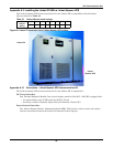
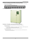
UPS Interconnection Kits
94
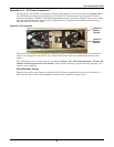
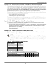
Appendix A.4.2 Status/Control Connections - Liebert Series 300 UPS Interconnection Kit
The status/control interface is the Status/Control Terminal Block. The connection of the Status/Con-
trol Terminal Block is described in the Figure 137 - Control wiring diagram—Liebert FS cabi-
net - manually operated circuit breaker. Refer to this drawing to ensure that the adequate
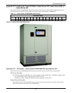
connections will be performed. If multiple Liebert FS units are connected to the same UPS DC bus,
refer to Figure 129 - Control wiring—external interconnect diagram, Liebert FS cabinet to
Liebert Series 610 UPS module to perform the Status/Control connections between each
Liebert FS.
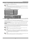
This interconnection kit includes status/control connections that enable transfer of signals between
the Liebert FS system(s) and the UPS system such as:
• Circuit breaker status (closed/open); and
• Undervoltage relay coil excitation voltage
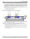
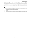
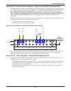
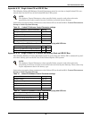
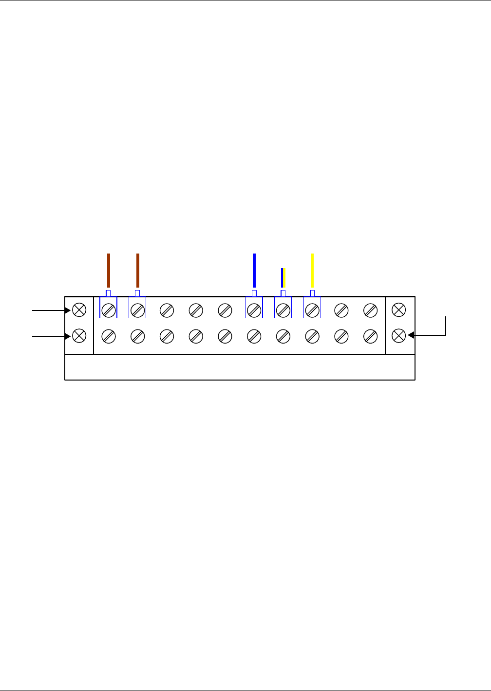
Figure 101 Liebert Series 300 status/control terminal block wiring
The recommended gauge for status/control connection wires is 16 AWG - 600VDC (1.3mm
2
wire sec-
tion). Status/Control wires must be sized and installed in compliance with all applicable local,
regional and national regulations (e.g., National Electric Code for USA).
Appendix A.4.3 UPS Configuration - Liebert FS and Liebert Series 300
To optimize the integration between the Liebert Series 300 UPS system and the Liebert FS, some
parameters must be checked on the UPS system:
• The UPS rectifier walk-in time must be set at a value as low as possible. Contact your Liebert rep-
resentative if your unit has received the upgraded board that enables the setting of “rectifier
walk-in time” lower than standard.
• Ensure that the “auto battery self test” has been either disabled or upgraded to accommodate
Liebert FS integration.
42 3 5 7 8 961 10
B
l
u
e
Yellow/
Blue
Y
e
l
l
o
w
Two rows
Row for
installation of
contractor wire
connections
B
r
o
w
n
B
r
o
w
n