


System Overview
34
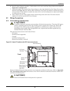
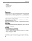
5.1.2 Power System
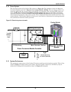
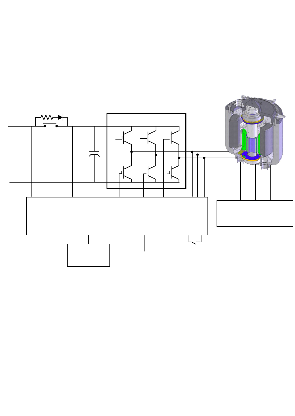
The electrical system of the Liebert FS is shown in Figure 36. The schematic shows the Magnetic
Levitation Module [see 5.1.7 - Magnetic Levitation Module (MLM)]. The pre-charge resistor and
contactor which limit the inrush current into the DC bus capacitors. The six-pulse IGBT power con-
verter (IGBT Power Conversion Module (PCM) on page 36) which is controlled by the Power
Conversion Module Controller (Power Conversion Module on page 33) and which also monitors
and controls the operation of the entire system. These components are housed within the Power Con-
version Module. The Flywheel Module is shown as a cross-section to illustrate the rotating group and
the synchronous reluctance motor-generator.
Figure 36 Electrical system schematic
5.1.3 System Performance
The maximum output power of the Liebert FS varies according to the duration required. This is illus-
trated in Figure 5 (output power versus time). Increased power, duration or redundancy may be
achieved by adding units in parallel as shown in Figures 2 through 4.
Magnetic Levitation
Module
Control
Panel
DC Monitoring
Motor Generator Controls
Power Conversion Module Controller
COM
AU Auxiliary
Backup
Remote Monitoring
& Controls (Optional)
Speed
Sensors
Temperature
Sensors
Position
Sensors
To UPS
Battery
Input
Soft Start
IGBT Power Converter
+
-
Flywheel Module