


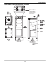
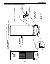
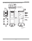
Installation Drawings
132
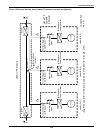
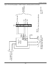
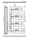
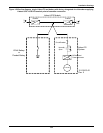
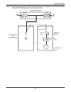
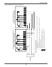
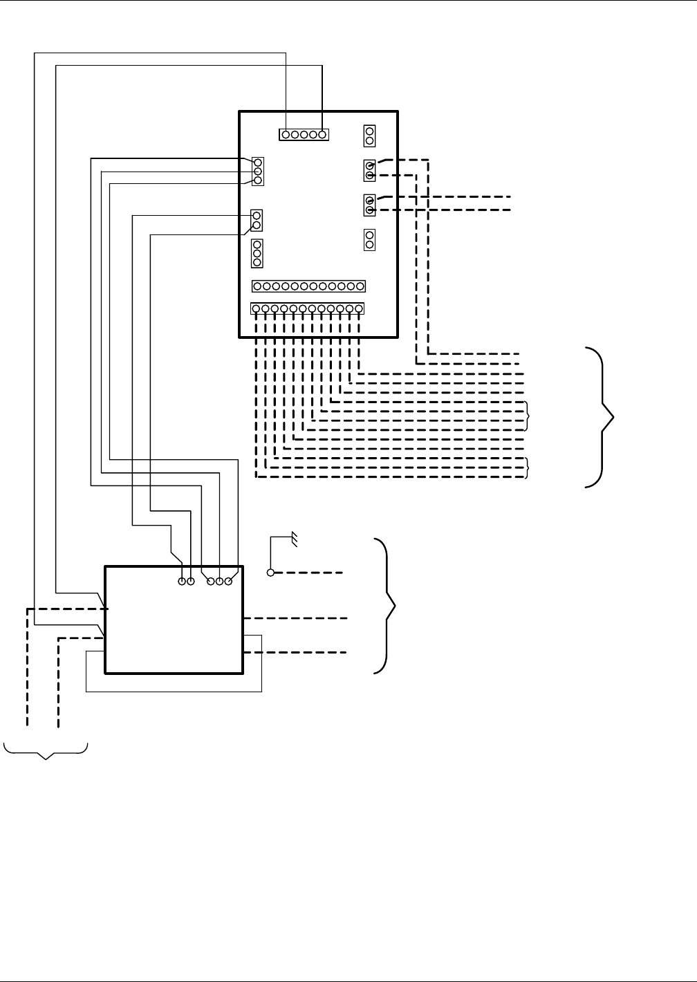
Figure 140Control wiring diagram—Liebert FS - optional electrically operated circuit breaker Liebert
Npower units
TB3
TB1
TB2
TB5 TB9
P2
TB8
400
401
113 Therm (In)
114 (Therm (Out)
Contractor to Provide Cables
to Liebert UPS Module
Yellow
Blue/Yellow
Blue
Brown
Brown
(-)
(-)
(+)
(+) (GND)
(-)
(+)
400
401
Liebert FS
Circuit Breaker
To Liebert FS
PCM DC
Output
Motor Oper. Power
Yellow N .C.
Blue/Yellow
Blue N.C.
Brown
Brown
12-100120-19
Rev. 0
Note:
1. PCM – Power Conversion Module
101 24 VDC +
102 24 VDC -
103 Control Relay Power
104 Motor Oper . On Signal
105 Motor Oper . Off Signal
106 N.O.
109 Logic GND
113 Therm (In)
114 Therm (Out)
112 (-)
110 (+)
108 N.C.
107 Common
TB4 TB6 TB7
Contractor to
Provide
Cables to
Liebert UPS
Module
Breaker Aux.
Contacts
UVR
Control
Aux.
Contacts
UVR