


Operation
53
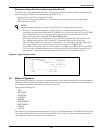
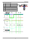
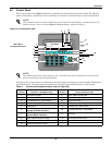
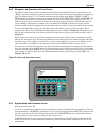
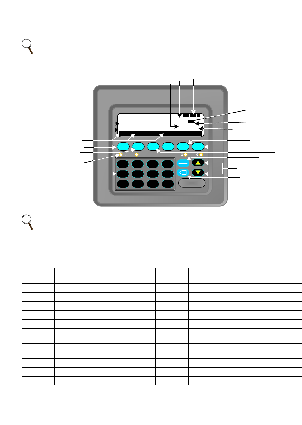
6.2 Control Panel
The Control Panel (see Figure 54) below represents the Control Panel on the Liebert FS. The dia-
gram is labeled as a reference for the various keys, functions and data found on the Control Panel.
Figure 54 Control panel view
Navigating the control panel is a simple process that involves responses to user prompts displayed in
the control panel. Using the panel to operate the unit will be described further in this section.
NOTE
(The actual locations of status indicators on the Control Panel display, corresponding to the
numbers below, may vary from Figure 54 depending on software version.)
NOTE
The control panel view is for reference only. Not all items will be enabled and visible on the
screen at the same time during operation
Table 4 Control panel keyboard layout (refer to Figure 54)
Keyboard
Location Operation / Navigation Keys
Keyboard
Location Screen Indication Keys
1 Numerical Keypad 11 SOC: State of Charge Bar
2 LEDs used for Servicing 12 SOC: State of Charge Value
3 F2 Shutdown key - Main Screen 13 PWR: Bus Power
4 F1 Start Up key - Main Screen 14 F5 More Information key - Fault Screen
5 Soft Menus 15 F6 Menu key - Main Screen
6
STATUS: System status (see 6.2.3 -
System STATUS Indicators)
16 F3 Clear Fault key - Fault Screen
7
MODE: System mode (see 6.2.2 -
System MODE Indicators)
17 Enter key
8 BUS: Internal DC Bus Voltage 18 Scroll Up and Down keys
9 RPM: Flywheel Rotation Speed 19 Backspace
10 Power and Options: On/Off
F1 F2 F3 F4 F5 F6
X
DISCHARGE
MODE:
STATUS:
OK
SOC:
SOC:
BUS:
PWR:
RPM:
93.3%
500V
190.2kW
0 1 2 3
. 4 5 6
- 7 8 9
50652
LIEBERT FS
MENU SHUTDN LOCK
I
!
D V U C P
See Table 4
for keyboard layout
8
9
11
12
13
14
15
16
17
18
19
1
2
3
4
5
6
7
10