


Installation Drawings
114
Appendix D.2 Other Liebert FS Drawings
Following is a list of additional Liebert FS drawings that are available for distribution. These draw-
ings are not directly linked to any specific Liebert FS model number, because most of them are appli-
cable to Liebert FS cabinets connected in parallel and we do not have a unique model number to
identify such units.
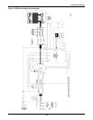
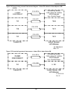
Parallel Liebert FS Cabinets – Two - Three Cabinets, no DC Junction Box
• 12-100120-04 – Control Wiring, Liebert Series 610, 600T, 600, 300
• 12-100120-14 – One Line Diagram
• 12-100120-10 – Control Wiring, Paralleled Units
• 12-100120-20 – One Line Diagram, Paralleled Units
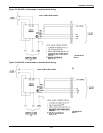
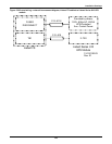
Parallel Liebert FS Cabinets – Four-Eight Cabinets with DC Junction Box
• 12-100120-17 – One Line Diagram
• 12-100120-10 – Control Wiring, Paralleled Units
• 12-100120-20 – One Line Diagram, Paralleled Units
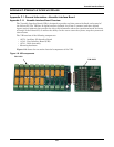
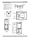
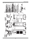
Single Liebert FS Cabinets – Additional Elevation Drawings
• 12-100120-11 – Liebert FS Custom Configuration without Circuit Breaker
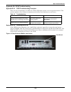
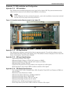
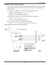
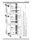
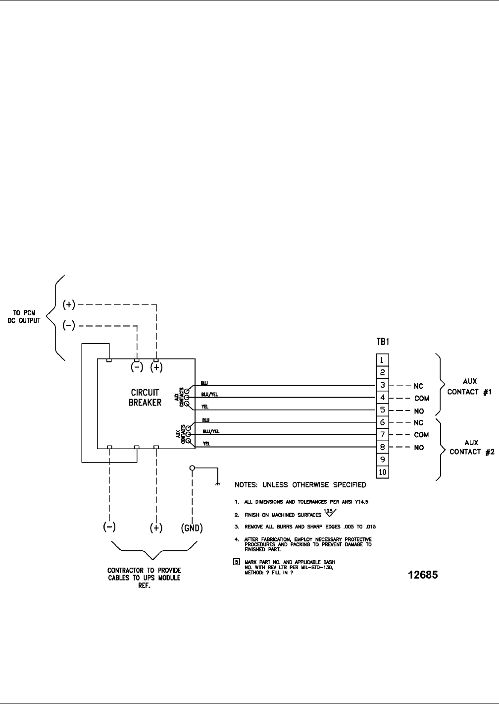
Figure 120 No UVR, circuit breaker to terminal block wiring
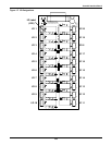
Note: PCM is UPS module.