


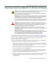

Installing Optional Network Expansion Module (NEM)
DFE-Platinum Series Hardware Installation Guide 3-3
Installing Optional Network Expansion Module (NEM)
RefertoyourreleasenotesortheEnterasys Networkswebsiteforthelatestavailable
networkexpansionmodule.
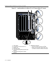
APhillipsscrewdriverisrequiredtoinstallanoptionalnetworkexpan sionmoduleinto
the7H4385‐49.
InstallingaNEMinvolves
•removingthesafetycover
•removingthecoverplatefromtheDFEmodule(7H4385‐49),
• attachingthenetwork
expansionmodule,and
•replacingthesafetycover.
RefertotheinstallationinstuctionsshippedwiththeNEMfordetails.
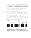
Backplane Connections and Installation Rules
ThefollowingsectionsdescribetheFTM1andFTM2backplaneconnections,andthe
hardwareconfigurationruleswheninstallingfirst(6x1xx),second(6x2xx),third(6x3xx),
andfourth(7xxxxx)generationmodulesintothesameMatrix E7chassis.
FTM1 and FTM2 Connectivity
TheMatrix E7(6C107)chassishasbackplanesreferredtoasFTM1andFTM2.The7xxxxx
DFE modulesuseFTM2forhighspeedcommunicationtoeachotherandoperateasone
switchingunitwithasingleIPaddress.Thetrafficthroughthesemodulesdoesnot
connecttoFTM1exceptthroughanFTMbridgingmodule
suchasthe7H4382‐25,
7H4382‐49,7H4383‐49,orthe7H4385‐49.InstallationGuidesforthesebridgingmodules
arelocatedontheEnterasysNetworksWorldWideWebsite:http://www.enterasys.com/
support/manuals.
Note: Install any optional equipment before proceeding to “Backplane Connections and
Installation Rules” on page 3-3 for an explanation of the rules to install different series
modules in a Matrix E7 chassis.
Note: A lowercase x indicates the general use of an alphanumeric character (for example,
6x1xx, the x’s indicate a combination of numbers or letters).