


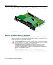
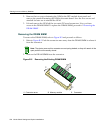
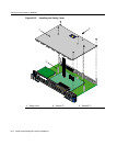


Gaining Access to Memory Modules
B-12 Mode Switch Settings and Option Installations
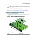
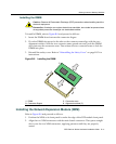
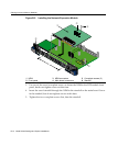
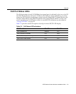
Figure B-9 Installing the Network Expansion Module
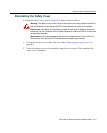
3. UsetwoofthesavedcoverplatescrewstofastentheNEMtotheDFE modulefront
panel,butdonottightenscrewsatthistime.
4. InsertthesavedstandoffthroughtheNEMtothestandoffonthemainboard.Screw
inthestandoff,butdonottightenscrewsatthistime.
5. Tighten
thetwocoverplatescrewsfirst,thenthestandoff.
1 NEM 3 NEM connectors 5 Coverplate screws (2)
2 Front panel 4 Main board connectors 6 Standoff
1X
G
R
O
U
P
1
G
R
O
U
P
2
11X
13X
23X
OFFLINE/
RESET
COM
CPU
M
G
M
T
GR
OUP
SELECT
GR
OUP
1
2
3
4
5
6
7
8
9
10
11
12
POE
12
X
14X
24X
G
R
O
U
P
3
25X
35X
26X
36X
G
R
O
U
P
4
37X
47X
38X
48X
1
2
3
4
48V --- 20A
MAX
OPTIONAL
PO
WER INPUT
G
R
O
U
P
1
1X
7
H
4
3
8
5
-
4
9
F
AST ENET
DFE
1
2
3
4
5
6
1
2
3
4
5
6
7G-6MGBIC-A
Ä
À
Á
Â
Ã
Å