


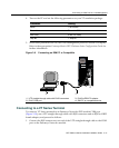
Connecting to the Network
DFE-Platinum Series Hardware Installation Guide 3-17
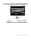
b. EachtimetheGROUPSELECTbuttonispressedforlessthatonesecond,the
GROUPLEDlightsupinsequence,indicatingwhichGroupisselected.The
receiveandtransmitactivityforthatgroupofsegmentsisthenindicatedbythe
RXandTXLEDsforeachsegment.
c. Verifythatthecabling
beingusedisCategory5UTPwithanimpedancebetween
85and111 ohms.Iftheportistooperateat100 Mbps,category 5cablingmustbe
used.
d. Verifythatthedeviceattheotherendofthetwistedpairsegmentison,and
properlyconnectedtothesegment.
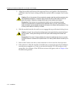
e. VerifythattheRJ45connectors
onthetwistedpairsegmenthavetheproper
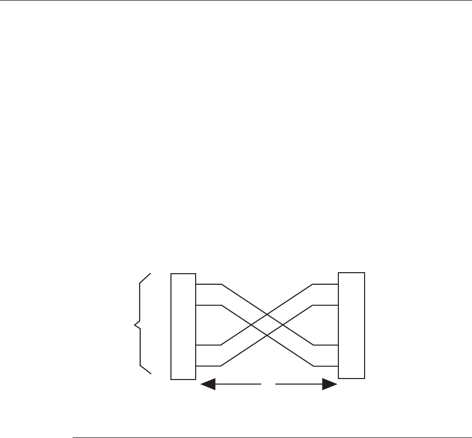
pinoutsandcheckthecableforcontinuity.Typically ,acrossovercableisused
betweenhubdevices.Astraight‐throughcableisusedtoconnectbetween
switchesorhubdevicesandanenduser(computer).RefertoFigure 3‐5and
Figure 3‐6for
four‐wireRJ45connections.RefertoFigure 3‐7andFigure 3‐8for
eight‐wireRJ45connections.
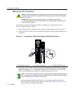
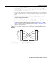
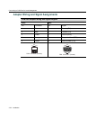
Figure 3-5 Four-Wire Crossover Cable RJ45 Pinouts, Connections Between Hub
Devices
1 RJ45 device port 3 RJ45-to-RJ45 crossover cable
2 Other device port 4 RX+/RX- and TX+/TX- connections.
These connections must share a common color pair.
TX+
TX
RX+
RX 2
1
3
6
TX+
TX
2
1
3
6
RX+
RX
ÀÁ
Â
Ã