


Preparing to Install into a Matrix E7, N1, N3, N5, or N7 Chassis
3-10 Installation
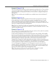
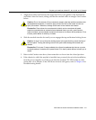
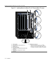
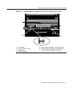
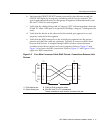
Figure 3-2 Installing Module into Matrix E7 or N7 Chassis (Matrix E7 shown)
1 Card guides 7 Backplane connectors
2 Slot number 6 (Left-most slot is 1) • Top two connectors (power and FTM2
3 Module card • Bottom two connectors (power and FTM1)
4 Metal back panel (no bottom connectors in Matrix N7chassis)
5 Upper/lower locking tabs (in proper open
position)
6 Upper/lower locking tab (in closed
position)
1
SERIES
E7
45
6
7
23
50/60Hz
LINE
100-125V~12A
200-240V~6A
50/60Hz
LINE
100-125V~12A
200-240V~6A
ACON
1
0
POWER FAN
PS1
50/60Hz
LINE
100-125V~12A
200-240V~6A
50/60Hz
LINE
100-125V~12A
200-240V~6A
ACON
1
0
POWER FAN
PS2
1X
G
R
O
U
P
1
G
R
O
U
P
2
11X
13X
23X
OFFLINE/
RESET
COM
CPU
MGMT
GROUP
SELECT
GROUP
1
2
3
4
5
6
7
8
9
10
11
12
POE
12X
14X
24X
G
R
O
U
P
3
25X
35X
26X
36X
G
R
O
U
P
4
37X
47X
38X
48X
DFE
7H4385-49
FAST ENET
1
2
3
4
48V --- 20A MAX
OPTIONAL
POWER INPUT
Ä
Ä
Å
Å
ÁÆ
Ã
Â
À