


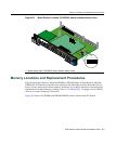
Memory Locations and Replacement Procedures
DFE-Platinum Series Hardware Installation Guide B-3
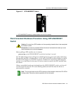
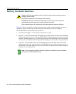
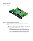
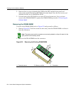
Figure B-1 Mode Switch Location (7H4385-49 shown without safety cover)
Memory Locations and Replacement Procedures
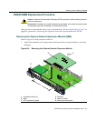
IftheDualIn‐lineMemoryModule(DIMM)orDRAMSingleIn‐lineMemoryModule
(SIMM)(FLASHmemory)needstobereplaced,thefollowingsectionsdescribehowto
access,locate,andreplacethesememorymodules.Ifyouhavequestionsconcerningthe
replacementofeithermemorymodule,referto“GettingHelp”
onpage xviiifordetails
onhowtocontactEnterasys Networks.
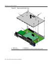
Figure B‐2showstheDIMMandDRAMSIMMlocationsonthemainPCboard.
1 Mode switch pack (7H4385-49 shown without safety cover)
1
2
3
4
5
6
1
2
3
4
5
6
7G-6MGBIC-A
1X
G
R
O
U
P
1
G
R
O
U
P
2
11X
13X
23X
OFFLINE/
RESET
COM
CPU
MGMT
GR
OUP
SELECT
GR
OUP
1
2
3
4
5
6
7
8
9
10
11
12
POE
12
X
14X
24X
G
R
O
U
P
3
25X
35X
26X
36X
G
R
O
U
P
4
37X
47X
38X
48X
1
2
3
4
48V --- 20A MAX
OPTIONAL
PO
WER INPUT
G
R
O
U
P
1
1X
7
H
4
3
8
5
-
4
9
F
AST ENET
DFE
12345678
ON
À