


Index-1
Index
Numerics
100BASE-TX
connection 3-15
requirements 2-3
10BASE-T
connection 3-15
requirements 2-2
7H4385-49
introduction to 1-3, 1-4
specifications for A-1
C
Cable connections
7H4382-49 3-15
UTP 3-15
Cable specifications
100BASE-TX network 2-3
10BASE-T network 2-2
CLI command
introduction to 1-5
COM port connections
IBM PC or Compatible Device 3-20
Modem 3-22
VT Series Terminal 3-21
what is needed 3-20
Connecting to the network 3-15
Connectivity
DFE module and network expansion module 1-5
introduction to 1-4
Console port
pinout assignments A-2
D
DFE Modules and optional NEM
introduction to 1-3
DFE series modules
overview of capabilities 1-2
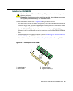
DIMM
installing DIMM B-11
replacement procedures for B-3
E
Electromagnetic Compatibility (EMC)
requirements A-3
F
FTM bridge function
introduction to 2-2
G
Getting Help
instructions for xviii
GROUP SELECT button
use of the 4-2
I
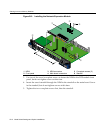
Installation
connecting to the Network 3-15
module into Matrix E7 or N7 chassis 3-7
module into Matrix N1, N3, N5 chassis 3-11
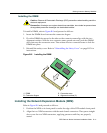
optional network expansion module 3-3
L
LANVIEW Diagnostic LEDs
use of 1-6
LANVIEW LEDs
use of 4-1
Local Management
COM port connections 3-20
introduction to 1-5
Login
administratively configured 3-28
M
Management
use of 1-5
Management (MGMT) LED
function of 4-1
Matrix E7 or N7 chassis
module installation into 3-7
Matrix N1, N3, N5 chassis
7H4385-49 installation into 3-11
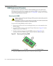
Memory
replacement of DIMM B-10
replacement of DRAM SIMM B-7
Memory locations
DIMM and SIMM B-3
Mode Switch
setting of B-2
Module coverplate
removal of B-7
Module features 1-3
N
NEM 3-3
Network
connecting to 3-15