


Backplane Connections and Installation Rules
3-6 Installation
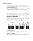
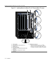
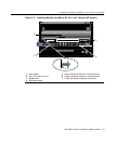
Example 5 (Figure 3-1, E)
Showschassisslots1and5populatedwith6x2xxand6x1xxmodules,respectively;slots2
through4withDFE moduleswithoutabridgingmodule;andslots6and7with6x3xx
modules.
Inthismodulearrangement,the6x2xxand6x1xxmodulesinslots1and5canonly
communicatewitheachother,
becausethereisno6x3xxmoduleinoneofthefirstfive
slotstoserveastheproxybridgetocommunicatewiththe6x3xxmodulesinslots6and7.
The7x4xxxDFE modulesinslots2,3,and4willoperateunderoneIPaddress.Sincethere
isnoDFE
bridgingmodule,theDFE moduleswillnotcommunicatewithanyother
modulesinthechassis.
Rule:Inthisexample,theremustbeatleastone6x3xxseriesmodule,andabridging
moduleinanyoftheslots1through5toenablecommunicationsbetweenallgenerations
ofmodulesinthechassis.
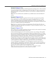
Example 6 (Figure 3-1, F)
ThemodulearrangementinthisexampleissimilartotheoneshowninFigure 3‐1,E and
describedinExample5.Theonlydifferenceisthatoneofthebridgingmodules
(7H4382‐25,7H4382‐49,7H4383‐49,or7H4385‐49)isinstalledinslot2,enablingall
modulestocommunicatewith
eachother.The7H4382‐49isusedinthisexample.
Rule:Inthisexample,thebridgingmoduleservesasboththeFTM1‐to‐FTM2bridgeand
thefive‐to‐sevenslotproxybridge.The6x3xxdoesnotserveasaproxybridgeinthis
configurationbecausethebridgingmoduleis
inaslotwithalowernumber.