


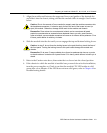
Backplane Connections and Installation Rules
3-4 Installation
TheseDFE moduleshaveconnectionstobothFTM1andFTM2backplanes,enablingthem
torouteframesbetweenthetwobackplanesandallmodulesinthe6C107chassis.
However,theolderfirst(6x1xx),second(6x2xx),andthird(6x3xx)generationmodules
arestillmanagedusingtheirownLocalManagementandarenotsubjectto
management
bytheDFE modulemanagemententity.
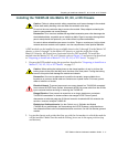
TheMatrix N1(7C111),Matrix N3(7C103)andMatrix N7(7C107)chassishaveonlyFTM2
connectionsandsupportonlyDFE modules.TheMatrix N5(7C105‐P)hasFTM2
connectionsandalsosupportsPoE‐compliantDFE m odules.
Module Placement and Installation Rules
TheDFE‐PlatinummodulescanbeinstalledinaMatrix E7(referto“Matrix E7Chassis
ModulePlacement,”below,forplacementrules),Matrix N1,Matrix N3,Matrix N5,or
Matrix N7chassis.TheMatrix N1,Matrix N3,Matrix N5,andMatrix N7chassissupport
onlyDFESeriesmodulesandtherearenoparticularrulesforinstallingmodules.
Matrix E7 Chassis Module Placement
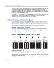
DependingonthemodulesbeinginstalledintheMatrix E7chassisandtohelpensure
properoperation,considerthefollowingexamplesandrulesformoduleplacementinthe
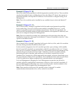
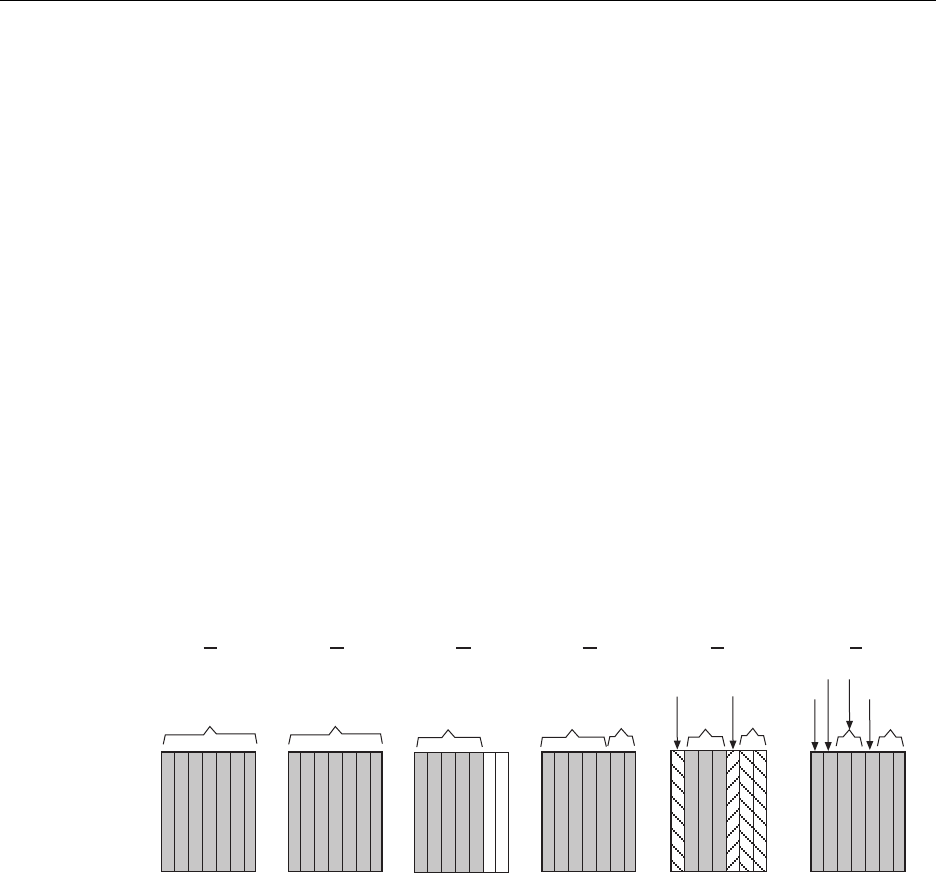
chassis.Figure 3‐1showssixexamplesofchassismoduleplacement.Theseexamplesare
describedbelowalongwiththeapplicablemoduleplacementrule.
Figure 3-1 Examples, Module Placement in Matrix E7 Chassis
Example 1 (Figure 3-1, A)
ShowsthechassisfullypopulatedwithDFE modules(7xxxxx).Thesemodules
communicatewitheachotherviatheFTM2chassisbackplaneandactasasingle
switchingentitywithoneIPaddress.TheDFE modulesareconfiguredusingaCommand
LineInterfacesetofcommands.
Rule:DFE modulescanbeinstalledinanyavailablechassis
slotintheMatrix E7chassis.
7XXXXX7H43X-XX
6X3XX
6X3XX
6X2XX
6X1XX
1 2 3 4 5 6 7
6X1XX
6X2XX
+
6X3XX
6X3XX
1 2 3 4 5 6 7
6X1XX
6X2XX
1 2 3 4 5 6 7
6X3XX
1 2 3 4 5 6 7
7XXXXX
1 2 3 4 5 6 7 1 2 3 4 5 6 7
6X3XX
6X3XX
6X2XX
7XXXXX
6X1XX
A EDCB
F