


Setup & Operation 2. Specifications
12 G10 / G20 Rev.2
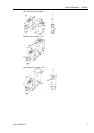
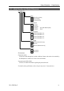
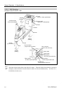
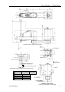
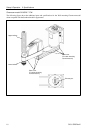
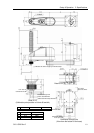
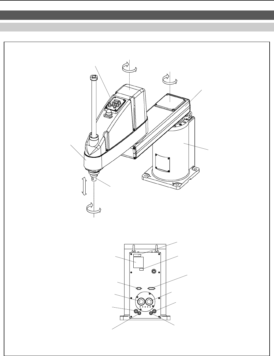
2.3 Part Names and Outer Dimensions
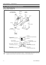
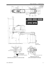
2.3.1 Table Top Mounting
Standard-model : G10/G20-***S
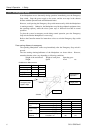
+
−
+
−
+
−
+
−
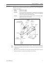
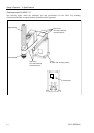
Joint #3 and #4
brake release button
Joint #2
(rotating)
Joint #2
(rotating)
Joint #3
(up and down)
Joint #4
(rotating)
Arm #1
Arm #2
Base
Shaft
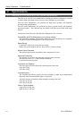
MT label
(only for custom specification)
Signature label
(Serial No. of Manipulator)
Signal cable
Power cable
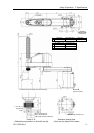
Fitting (black)
for ø 6 mm pneumatic tube
User connector
(15-pin D-sub connector)
User connector
(9-pin D-sub connector)
CE label
Fitting (black)
for ø 4 mm pneumatic tube
Fitting (white)
for ø 6 mm pneumatic tube
Fitting (white)
for ø 4 mm pneumatic tube
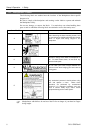
The brake release button affects both Joints #3 and #4. When the brake release button is pressed in
emergency mode, the brakes for both Joints #3 and #4 are released simultaneously.
)
NOTE