


Setup & Operation 2. Specifications
G10 / G20 Rev.2 17
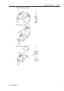
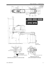
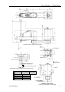
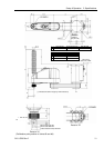
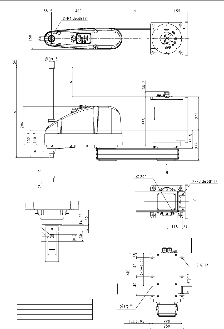
Reference hole
(Tolerance applies
to the pin hole)
Conical hole ø4,90°
1 mm flat cu
t
Max.ø18 through hole
ø25 h7 shaft diameter
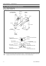
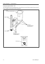
90 or more
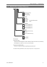
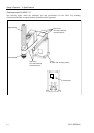
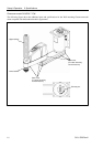
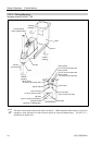
Space for cables
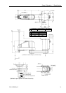
(*) indicates the stroke margin by mechanical stop.
ø39.5 mechanical stop diameter
Detail of “A”
(
Calibration
p
oint
p
osition of Joints #3 and #4
)
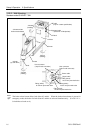
Reference through hole
(View from the bottom of the base)
Detail of “B”
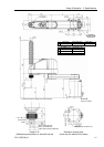
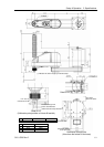
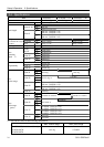
G10-65*SW G10/G20-85*SW G20-A0*SW
a 250 450 600
G10/G20-**1SW G10/G20-**4SW
b 180 420
c -27.5 212.5
d 420 660