


Setup & Operation 3. Environments and Installation
38 G10 / G20 Rev.2
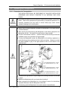
3.7 User Wires and Pneumatic Tubes
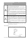
CAUTION
■
Only authorized or certified personnel should be allowed to perform wiring.
Wiring by unauthorized or uncertified personnel may result in bodily injury and/or
malfunction of the robot system.
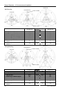
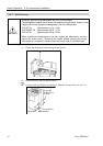
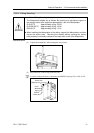
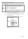
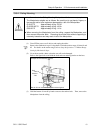
User electrical wires and pneumatic tubes are contained in the cable unit.
Electrical Wires
Rated Voltage
Allowable
Current
Wires Nominal Sectional Area Outer Diameter Note
AC/DC30 V 1 A 15 0.211 mm
2
ø8.3±0.3 mm
Shielded
Maker Standard
Suitable Connector JAE
DA-15PF-N (Solder type)
15 pin
Clamp Hood JAE
DA-C8-J10-F2-1R (Connector setscrew: #4-40 NC)
Suitable Connector JAE
DE9PF-N (Solder type)
9 pin
Clamp Hood JAE
DE-C8-J9-F2-1R (Connector setscrew: #4-40 NC)
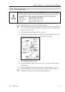
Pins with the same number, indicated on the connectors on both ends of the cables, are
connected.
Pneumatic Tubes
Max. Usable Pneumatic Pressure Pneumatic Tubes Outer Diameter × Inner Diameter
2
ø6 mm × ø4 mm
0.59 MPa (6 kgf/cm
2
: 86 psi)
2
ø4 mm × ø2.5 mm
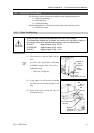
Fittings for ø6 mm and ø4 mm (outer diameter) pneumatic tubes are supplied on both ends
of the pneumatic tubes.
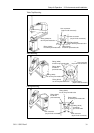
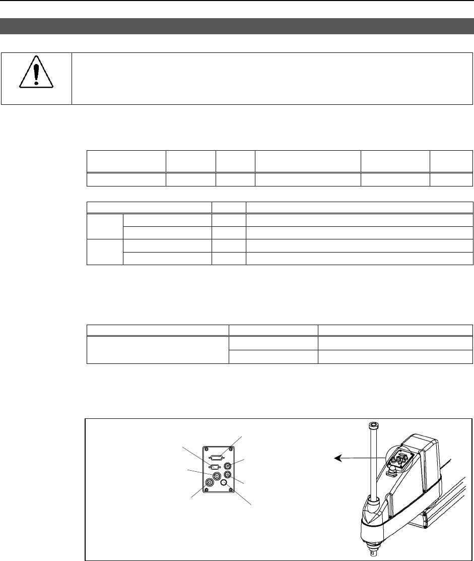
Common Parts
Fitting (white) for
ø6 mm pneumatic tube
Fitting (black) for
ø6 mm pneumatic tube
Brake release
button switch
15-pin D-sub connector
Fitting (black) for
ø4 mm pneumatic tube
Fitting (white) for
ø4 mm pneumatic tube
9-pin D-sub connector