


Setup & Operation 3. Environments and Installation
30 G10 / G20 Rev.2
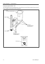
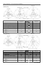
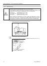
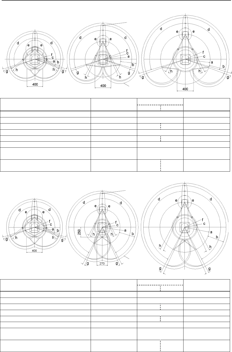
G10-65**W
G10/G20-85**W
G20-A0**W
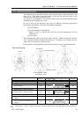
Wall Mounting
Center of Joint#3
Maximum space
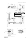
G10/G20-85*
G10-65**W
SW CW
G20-A0**W
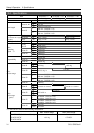
a
Length of Arm #1 (mm)
250 450 600
b
Length of Arm #2 (mm)
400 400 400
c
(Motion range)
306.5 207.8 218.3 307
d
Motion range of Joint #1 (degree)
107 107 107
e Motion range of Joint #2 (degree) 130 152.5 151 152.5
f
(Mechanical stop area)
291.2 183.3 285.4
g
Joint #1 angle to hit mechanical stop
(degree)
3 3 3
h
Joint #2 angle to hit mechanical stop
(degree)
3.5 3.5 5 3.5
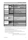
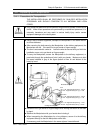
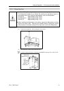
G10-65**R
G10/G20-85**R
G20-A0**R
Ceiling Mounting
Center of Joint#3
Maximum space
G10/G20-85*
G10-65**R
SR CR
G20-A0**R
a
Length of Arm #1 (mm)
250 450 600
b
Length of Arm #2 (mm)
400 400 400
c
(Motion range)
306.5 207.8 218.3 307
d
Motion range of Joint #1 (degree)
107 152 152
e Motion range of Joint #2 (degree) 130 152.5 151 152.5
f
(Mechanical stop area)
291.2 183.3 285.4
g
Joint #1 angle to hit mechanical stop
(degree)
3 3 3
h
Joint #2 angle to hit mechanical stop
(degree)
3.5 3.5 5 3.5