Setup & Operation 5. Motion Range
68 G10 / G20 Rev.2
5.4 Standard Motion Range
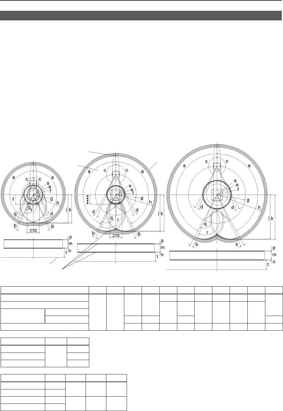
The following “motion range” diagrams show the standard (maximum) specification.
When each Joint motor is under servo control, the center of Joint #3’s (shaft’s) lowest
point moves in the areas shown in the figure.
“Area limited by mechanical stop” is the area where the center of Joint #3’s lowest point
can be moved when each joint motor is not under servo control.
“Mechanical stop” sets the limited motion range so that the center of Joint #3 cannot move
beyond the area mechanically.
“Maximum space” is the area that contains the farthest reach of the arms. If the
maximum radius of the end effector is over 60 mm, add the “Area limited by mechanical
stop” and “radius of the end effector”. The total value is specified as the maximum area.
Table Top Mounting
Center of Joint#3
Maximum space
Motion range
rea limited by mechanical stop
Base mounting face
G20-A0**
G10/G20-85**
G10-65**
**** : G10/G20-85*S : 207.8
G10/G20-85*C : 218.3
a b c d e f g h j k q
G10-65** 199.4 212.4 250 650 620.7 626.6
G10/G20-85*S
Z: 0 to –360
152.5° 3.5°
207.8
152.5
G10/G20-85*C
Z: –360 to –390
151° 5°
183.3
218.3
450 850 797.3 807.8
151
G20-A0**
152° 3°
152.5° 3.5° 285.4 307 600 1000 929.8 943.8 152.5
r s
G10-65** 139.4
G10/G20-85** 123.3
G20-A0**
156
225.4
m n p t
G10/G20-**1S 180
G10/G20-**4S 420
5 5 393.5
G10/G20-**1C 150
G10/G20-**4C 390
1 1.8 355.5
(°: degree)
)
NOTE
In the range Z: –360 to –390 mm, the area is limited by interference of the Manipulator body and the arm.
