


Setup & Operation 3. Environments and Installation
G10 / G20 Rev.2 29
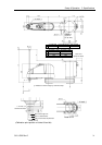
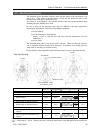
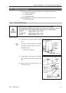
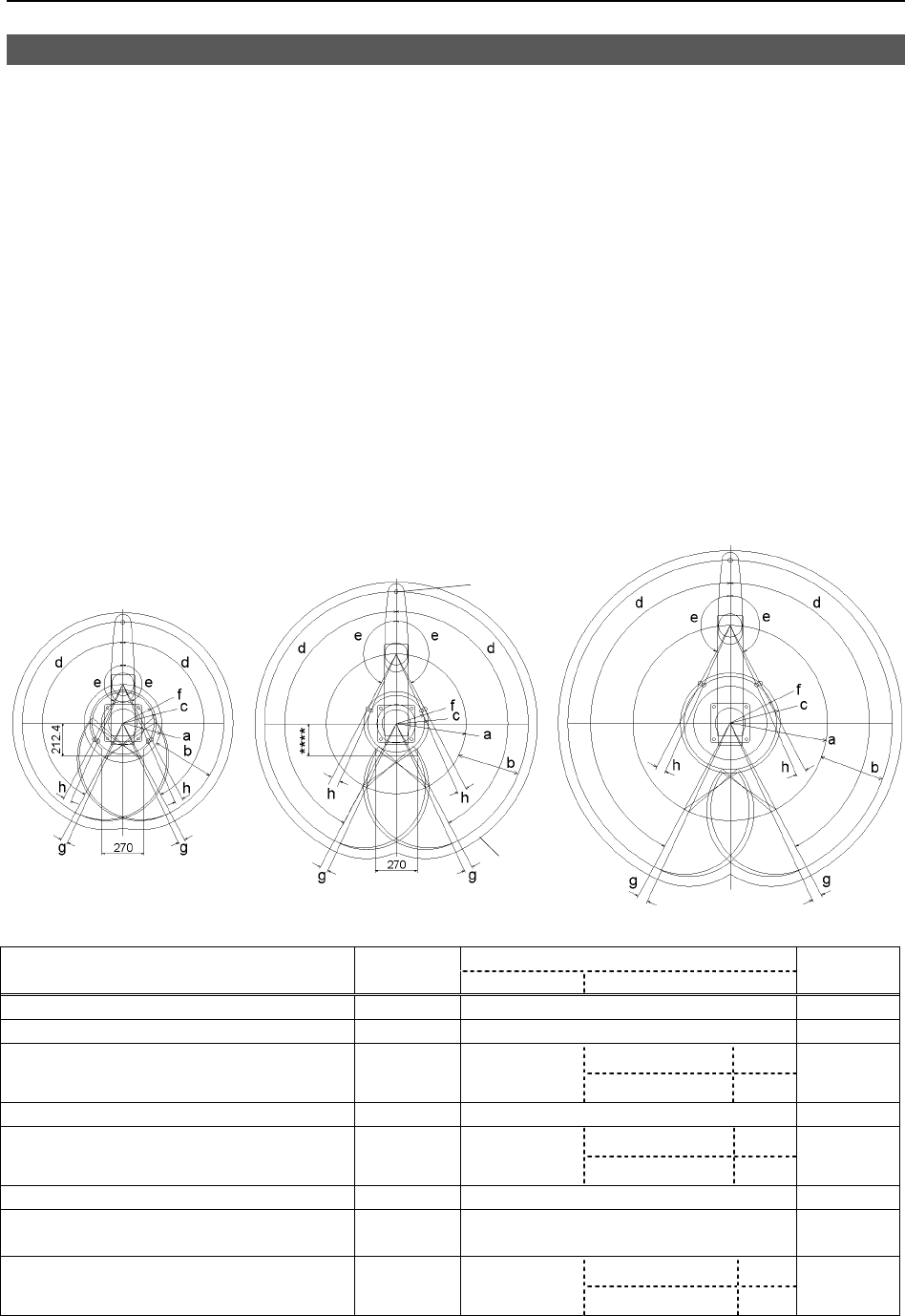
3.3 Mounting Dimensions
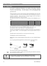
The maximum space described in figures shows that the radius of the end effector is 60
mm or less. If the radius of the end effector exceeds 60 mm, define the radius as the
distance to the outer edge of maximum space.
If a camera or electromagnetic valve extends outside of the arm, set the maximum range
including the space that they may reach.
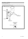
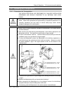
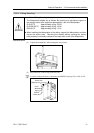
Be sure to allow for the following extra spaces in addition to the space required for
mounting the Manipulator, Controller, and peripheral equipment.
space for teaching
space for maintenance and inspection
(Ensure a space to open the rear side cover and the maintenance cover for
maintenance.)
space for cables
The minimum bend radius of the power cable is 90 mm. When installing the cable, be
sure to maintain sufficient distance from obstacles. In addition, leave enough space for
other cables so that they are not bent forcibly.
Ensure distance to the safeguard from the maximum motion range is more than 100 mm.
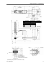
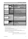
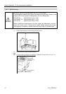
G10-65**
G10/G20-85**
G20-A0**
Table Top Mounting
Center of Joint#3
Maximum space
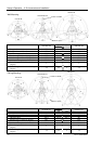
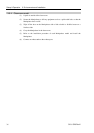
**** : G10/G20-85*S : 207.8
G10/G20-85*C : 218.3
G10/G20-85*
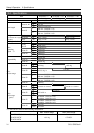
G10-65**
S C
G20-A0**
a
Length of Arm #1 (mm)
250 450 600
b
Length of Arm #2 (mm)
400 400 400
Z: 0 to −360 207.8
c
(Motion range)
212.4 207.8
Z:
− 360 ∼ −390 218.3
307
d
Motion range of Joint #1 (degree)
152 152 152
Z: 0 to −360
152.5
e Motion range of Joint #2 (degree) 152.5 152.5
Z:
−360 to −390
151
152.5
f
(Mechanical stop area)
199.4 183.3 285.4
g
Joint #1 angle to hit mechanical stop
(degree)
3 3 3
Z: 0 to −360
3.5
h
Joint #2 angle to hit mechanical stop
(degree)
3.5 3.5
Z:
−360 to −390
5
3.5
)
NOTE
In the range Z: –360 to –390 mm, the area is limited by interference of the Manipulator body and the arm.