


5 OPERATING ENVIRONMENTS AND STARTING PROCEDURES
S5U1C17801T1100 HARDWARE MANUAL
EPSON
15
(SOFTWARE EVALUATION TOOL FOR S1C17801)
5 Operating Environments and Starting
Procedures
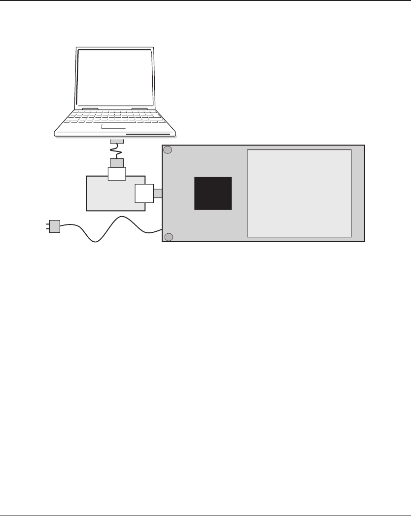
By connecting with your PC via the ICD board, the SVT17801 can be operated in accordance with commands ex-
ecuted by a debugger on the PC. The SVT17801 CPU board can be operated as stand-alone without using the ICD
board and PC. The following explains the connection and starting procedures required for each operation.
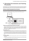
Software Simple Development Environments
The SVT17801 can provide simple development environments of software using the CPU board as a target. This
can be achieved by connecting the SVT17801 to your PC via the ICD board and using the S1C17 development tool
on the PC (such as GNU17 IDE, compiler and debugger included in the S5U1C17001C package).
USB cable
AC power adapter
ICD
board
S5U1C17001C
(Debugger)
C17801
B/W QVGA
LCD panel module
CPU board
Fig. 5.1.1 Software Simple Development Environments
Operation under Software Simple Development Environments
Under these operating environments,the target CPU (the S1C17801 on the CPU board) operates according to
commands executed by a debugger on your PC connected with the ICD board. A command executed by the
debugger is sent to the ICD board via USB to be analyzed and converted into a debug signal, and then sent
to the CPU board. The debugger on your PC can be used to download programs or data to the CPU board, or
debug programs by controlling their execution and stop.
Operating Mode of CPU
The "brk" command or debugging interrupts (such as forcible breaking operation by the debugger) from the
ICD board causes the target CPU (the S1C17801 on the CPU board) to stop executing the target program and
enter into debug mode (or break status). In this status, commands can be executed from the debugger on your
PC. LED on the ICD board lights in green during debug mode. On the other hand, the status where the target
CPU executes the target program is called normal mode. LED on the ICD board lights in red during normal
mode.
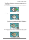
Connection and Start
The following describes connection and startup procedures to allow for the software simple development
environments.
(1) Connect the ICD board with the CPU board. Connect JICD 10 pin connector on the ICD board with the
counterpart on the CPU board. Then turn on the CPU board.