


15 LED/LCD BACKLIGHT CONTROL CIRCUIT WITH MFT0
S5U1C17801T1100 HARDWARE MANUAL
EPSON
37
(SOFTWARE EVALUATION TOOL FOR S1C17801)
15 LED/LCD Backlight Control Circuit
with MFT0
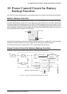
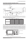
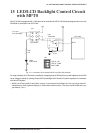
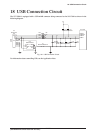
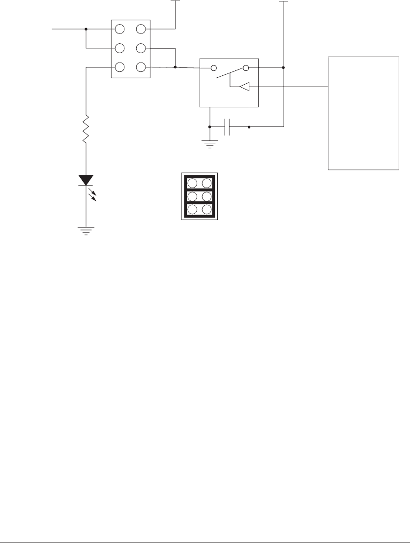
The SVT17801 is equipped with a LED that can be controlled by MFT0. The following diagram shows how the
EEPROM is connected to the SVT17801.
DIC-152-6P
1
1
5
3
5
3
2
6
4
2
4
G V
V
DD
J12 11pin
(LCD backlight)
V
DD
JP3
JP3
MFT0
U20
TS5A3166
R90
470
LED3
LT
W-170TK
C65
0.1µF
LCD_BL_ON
LCD_BL_PWM
D201_PWM
S1C17801
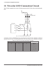
Fig. 15.1 Connection Circuit between MFT0 and LED/LCD Backlight
Pre-stage switching IC (TS5A3166) is switched by changing phase in MFT0 H/L areas, and brightness of the LED
can be changed visually by turning ON and OFF the backlight of LED and LCD panel repeatedly in accordance
with the MFT0 phase.
∗ MFT0 is an I/O port with 12 mA of drive current. A circuit shown in the figure 15.1.has a pre-stage switch IC,
which however can be replaced simply by a 470
Ω resistor for direct drive. (The drive current in this case is ap-
proximately 7 mA.)