


12 KEY INPUT CIRCUIT ON CPU BOARD
34
EPSON
S5U1C17801T1100 HARDWARE MANUAL
(SOFTWARE EVALUATION TOOL FOR S1C17801)
12 Key Input Circuit on CPU Board
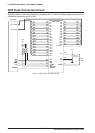
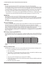
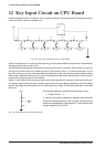
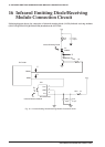
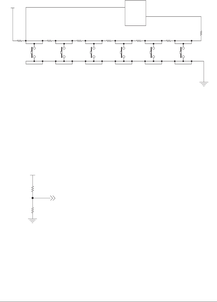
Switches connected to the SVT17801 (S1 - S6) are connected with the AD input port (AIN7) and input port (P31)
on the S1C17801 as shown in the figure 12.1.
AV
DD
AIN7
S1C17801
P31
S1 S2 S3 S4 S5 S6
5.1K
5.1K
3
4
3
4
3
4
3
4
3
4
3
4
1
2
1
2
1
2
1
2
1
2
1
2
5.1K
5.1K
5.1K
5.1K
5.1K
Fig. 12.1 Key Input Connection Circuit on CPU Board
In this circuit, the press of a switch is detected by the port (P31) status and the pressed switch is determined by
detecting an input value of AD (AIN7).
The mechanism of detecting the switch status by the port (P31) status is as follows: If all switches are open, the
port (P31) is in HIGH state as it is pulled up by the 35.7KΩ resistor (5.1KΩ x 7) as shown in the figure 12.1. If
any of the switches is pressed, on the other hand, the pull-down resistor value becomes smaller than the pull-up
resistor value, and this turns the port (P31) LOW. The mechanism of this circuit enables the press of any switch to
be detected by using interrupt or other method.
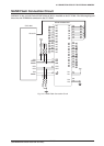
Figure 12.1 also indicates that the pressed switch can be determined by the variance of ratio between the pull-
up resistance value and the pull-down resistance value, because the ratio changes depending on the switch being
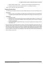
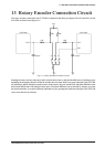
pressed. The change can be detected by an AD (AIN7) input value. Figure 12.2 shows the equivalent circuit of the
figure 12.1.
AVDD
R1
R2
V
Fig. 12.2 Equivalent Circuit of Single Key Input
The following equation is satisfied in this equivalent circuit:
V = R2/(R1+R2)AV
DD
"V" value for each switch is obtained by resistance values of R1 and
R2 that are obtained when the switch is pressed. Thus the pressed
switch can be determined by comparing the "V" value with the value
actually entered into AD (AIN7).