


11 LCD PANEL CONNECTION CIRCUIT
32
EPSON
S5U1C17801T1100 HARDWARE MANUAL
(SOFTWARE EVALUATION TOOL FOR S1C17801)
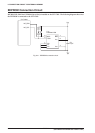
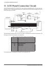
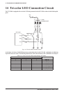
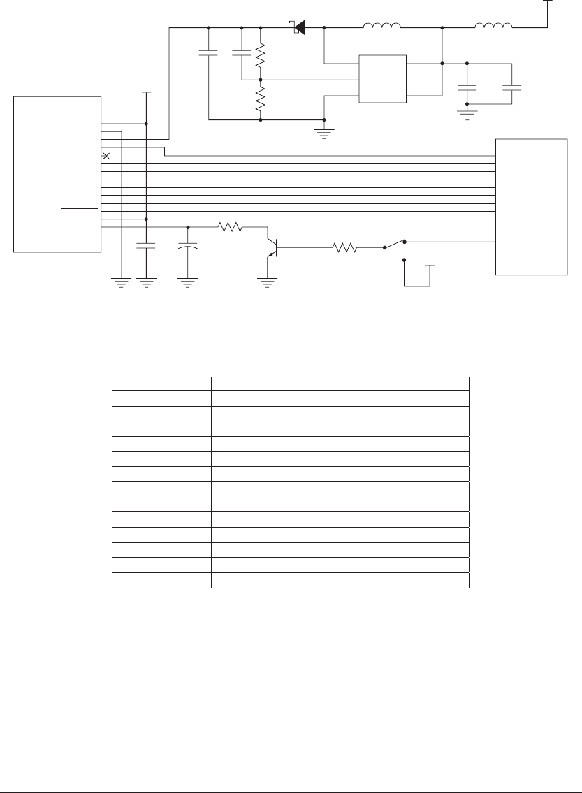
11 LCD Panel Connection Circuit
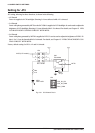
The S1C17801 has a built-in LCD controller (LCDC) that supports the monochrome STN LCD panel and paral-
lel interface. The SVT17801 is equipped with the QVGA panel module (EW32F92FLWP including driver) with a
built-in monochrome STN panel.
LCD panel module
(EW32F92FLWP)
VDD
VDD
R101 0
R102 1K
SW
VDD
V
SS
VLCD
FLM
NC
CL1
CL2
D0
D1
D2
D3
DISPOFF
VLED
VLSS
FPFRAME
FPLINE
FPSHIFT
FPDAT4
FPDAT5
FPDAT6
FPDAT7
FPDRDY
MFT0
C103
0.1µF
C104
47µF
C106
1µF
C107
4.7µF
C111
10µF
S1C17801
R103
2.2M
1%
R104
130K
1%
U101
TPS61040
L101
LQH32CN4R7M23L
L102
MPZ2012S601A
VDD
D101
B0530W-7-F
1
SW
FB
GND
VIN
EN
3
2 4
5
C105
22PF
Q105
MMBTA42-TP
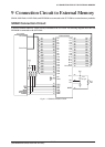
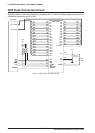
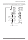
Fig. 11.1 LCD Panel Module Connection Circuit
This panel module is equipped with a 4-bit STN LCD panel, to which data bus is connected as shown above. The
following lists function of each signal on the module side.
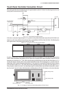
Table 11.1 Name and Function of Signal on LCD Panel Module
Signal Name Functionalities
VDD Logic power supply inside module
VSS GND of logic power supply inside module
VLCD LCD driver power supply
FLM Frame clock
CL1
Display data line clock
CL2
Display data shift clock
D0
Display data bus
D1
Display data bus
D2
Display data bus
D3
Display data bus
DISPOFF LCD ON/OFF Control (L:OFF, H:ON)
VLED Backlight power supply
VLSS Backlight power supply
For information about controlling the LCD panel, see the Application Note.