


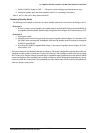

16 INFRARED EMITTING DIODE/RECEIVING MODULE CONNECTION CIRCUIT
S5U1C17801T1100 HARDWARE MANUAL
EPSON
39
(SOFTWARE EVALUATION TOOL FOR S1C17801)
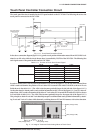
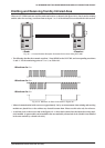
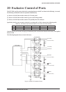
Emitting and Receiving from/by Infrared Area
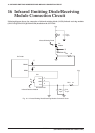
When two SVT17801 units are used for sender and receiver as shown in the figure 16.1.1, that is one for emitting
and the other for receiving, waveform from each part
➀ to ➂ of the infrared area are described in this section.
<Send> <Receive>
Fig. 16.1.1 Infrared Emission/Reception Evaluation Environment Using SVT17801
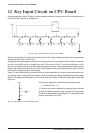
∗ The following describes the transmit waveform ➀ from REMO on the S1C17801, and corresponding waveforms
➁ and ➂. For the monitoring points of ➀ to ➂, see Table 16.1.
<Waveform for ➀>
<Waveform for ➁>
<Waveform for ➂>
Fig. 16.1.2 Waveform for Each Point Shown in Figure 16.1
∗ Infrared communication in this case covers approximately 3 m by our measurement when emitting and receiving
modules are placed face to face without any obstacle between them. Please use this value only for reference.
∗ A solid red circle on the receiver side in the figure 16.1.1. shows the location where the infrared receiving mod-
ule is installed. A spare module can be installed in the area marked by a dotted red circle. (Module is not installed
in the area marked by a dotted red circle.)