


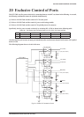
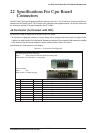
22 SPECIFICATIONS FOR CPU BOARD CONNECTORS
50
EPSON
S5U1C17801T1100 HARDWARE MANUAL
(SOFTWARE EVALUATION TOOL FOR S1C17801)
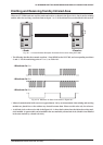
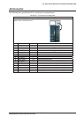
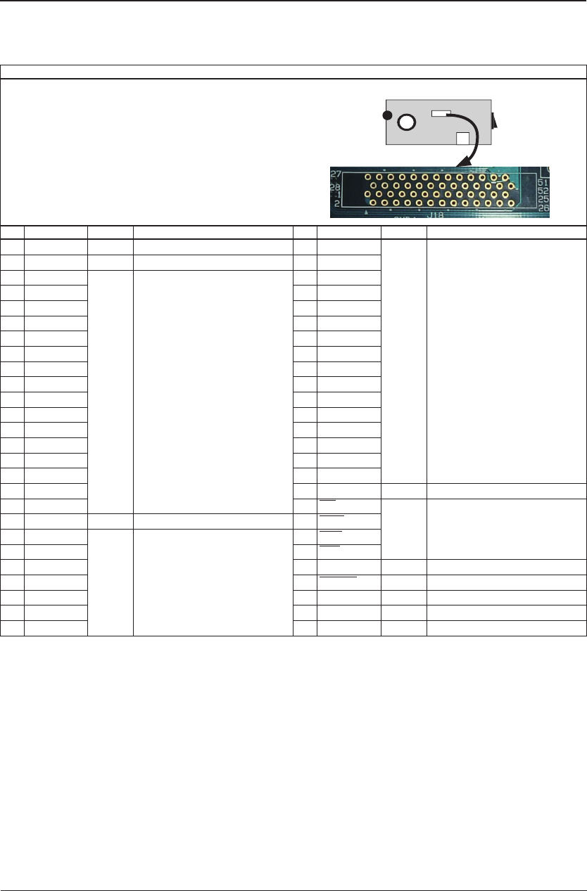
J18 Connector
The following shows specifications of J18, a connector for expansion board. This connector can be used for
connection with external bus and others. (The connector is not installed.)
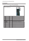
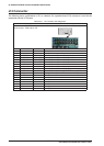
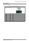
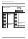
Table 22.6.1 J18 Connector Pin Assignment
Connector J18
Maker: HIROSE
Model number: FX2C-52P-1.27DSA(71)
Rear view of CPU board
No. Name I/O Functionalities No. Name I/O Functionalities
1 (+5V) – – 27 A7/P67 O | I/O External address bus |
General purpose I/O port
2 (+5V) – – 28 A8/P70
3 D0/P90 I/O | I/O External data bus | General
purpose I/O port
29 A9/P71
4 D1/P91 30 A10/P72
5 D2/P92 31 A11/P73
6 D3/P93 32 A12/P74
7 D4/P94 33 A13/P75
8 D5/P95 34 A14/P76
9 D6/P96 35 A15/P77
10 D7/P97 36 A16/P80
11 D8/PB0
37 A17/P81
12 D9/PB1 38 A18/P82
13 D10/PB2 39 A19/P83
14 D11/PB3 40 A20/P84
15 D12/PB4 41 A21/P85
16 D13/PB5 42 A22/P86
17 D14/PB6 43 N.C (TP26) – –
18 D15/PB7 44 RD /PA4 O | I/O Memory controller | General
purpose I/O port
19 N.C (TP25) – – 45 WRL /PA5
20 A0/P60 O | I/O External address bus |
General purpose I/O port
46 BSH /PA6
21 A1/P61 47 BSL /P60
22 A2/P62 48 P44 I/O General purpose I/O port
23 A3/P63 49 RESET I Reset signal
24 A4/P64 50 N.C (TP27) – –
25 A5/P65 51 (GND) – –
26 A6/P66 52 (GND) – –