


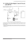
22 SPECIFICATIONS FOR CPU BOARD CONNECTORS
S5U1C17801T1100 HARDWARE MANUAL
EPSON
45
(SOFTWARE EVALUATION TOOL FOR S1C17801)
22 Specifications For Cpu Board
Connectors
The SVT17801 CPU board is equipped with five connectors (No. J6, J7, J8, J12 and J13). J6 can be used for con-
nection to the ICD board, and J7, J8, J12 and J13 for connection with expansion boards. J12 and J13 can be used
for connection with the LCD panel attached to the SVT17801.
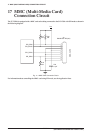
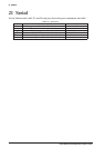
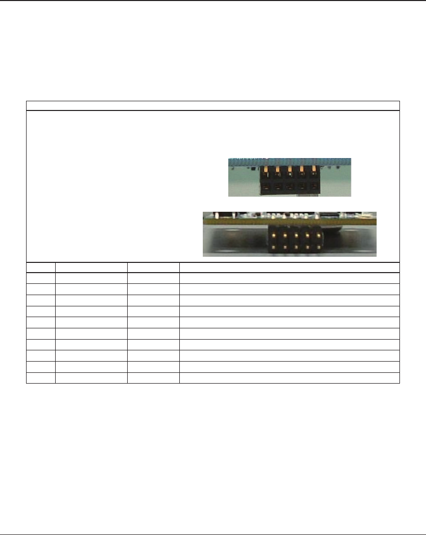
J6 Connector (to Connect with ICD)
J6 connector is used to connect the ICD board to the CPU board.
∗ Be careful not to plug this connector reversely. Doing so may damage both of the boards. See figures in the
Chapter 3 to check how the CPU board and ICD board are connected. (Face where the USB connector is installed
is the surface of the ICD board. Align this surface with the surface of the CPU board.)
Specifications for each connector are as follows:
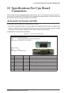
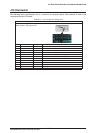
Table 22.1.1 J6 Connector Pin Assignment
Connector J6
(The right figures show the side view)
Maker: Japan Aviation Electronics Industry,Limited (JAE)
Model number: PS-10SD-D4T1-1 (receptacle)
Upper view of CPU board
(ICD board side)
Maker: Tyco
Model number: 9-103801-0 (plug)
Side view of ICD board
No. Name I/O Functionalities
1 DCLK O On-chip debugger clock output port
2 GND – Power ground (Connection with every pin is recommended.)
3 GND – Power ground (Connection with every pin is recommended.)
4 #RESET_OUT I Target reset signal input port
5 DSIO I/O On-chip debugger clock I/O port
6 TGT_EN I Target enable signal input port
7 DST2 O On-chip debugger status signal output port
8 N.C – –
9 VCC (+3.3V) – +3.3V power pin
10 VCC (+3.3V) – +3.3V power pin
10 2
9 1
2
1
10
9