


EPSON FX-2180 Service Manual Chapter 2 Operating Principles
2-4
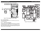
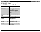
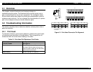
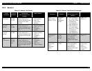
The table below identifies and describes the main components of the
control circuit on the C244 MAIN board.
Table 2-3. Main Components of the Control Circuit
Component IC Function(s)
Gate array
(E05B50**)
IC1 • System control
• Peripheral device control
CPU
(TMP96C141BF)
IC2
• Receives data from the host
computer and sends it to the input
buffer in RAM
• Extends the input data held in the
buffer to create image data
• Loads image data to the image data
buffer
• Transfers image data to the print
head
1 Mbit / 4 Mbit
PS-RAM
IC3 Contains the buffer and the working
area
2 Mbit PROM IC5 Contains the character tables and the
program that runs the CPU
Serial EEPROM
(AT93C46)
IC8 Contains data including:
• Default setting values
• Market data
• Mechanism and print head
parameters
SLA7024M IC9 Driver circuit for the CR motor
A2917SEB IC12 Driver circuit for the PF motor
Reset IC
(BH6150F)
IC15 Generates the reset signal at power on
and power down, and resets the CPU
and the gate array